DV251001 Microchip Technology, DV251001 Datasheet - Page 41
DV251001
Manufacturer Part Number
DV251001
Description
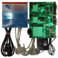
KIT DEVELOPMENT CAN MCP2510
Manufacturer
Microchip Technology
Specifications of DV251001
Main Purpose
Interface, CAN Controller
Embedded
Yes, MCU, 8-Bit
Utilized Ic / Part
MCP2510, MCP2515
Primary Attributes
Stand alone CAN Controller with SPI
Silicon Manufacturer
Microchip
Application Sub Type
CAN
Kit Application Type
Interface
Silicon Core Number
MCP2510, MCP2515
Kit Contents
Board Cable Power Supply CD
Lead Free Status / RoHS Status
Lead free / RoHS Compliant
Secondary Attributes
-
Lead Free Status / RoHS Status
na, Lead free / RoHS Compliant
Other names
DV251001R
DV251001R
DV251001R
Available stocks
Company
Part Number
Manufacturer
Quantity
Price
Company:

Part Number:
DV251001
Manufacturer:
MICROCHIP
Quantity:
12 000


M
B.1
B.2
2003 Microchip Technology Inc.
INTRODUCTION
FAQS
Appendix B. FAQs on Configuring the MCP2515
This section answers some frequently asked questions concerning the configuration of
the MCP2515 to assist those who are new to the device.
1. Why doesn’t the development tool successfully communicate on an
TABLE B-1:
2. The node is acknowledging messages in the Basic template but not
The MCP2515 is off the bus
(not in Normal mode).
The LPT port is not configured
correctly.
The bus rate is not set to match the
bus.
Oscillator frequency not set to match
hardware (F
formula).
Board is not connected to the
external bus.
external bus?
There are several possible reasons why this is the case. The following are the
most common problems:
displaying them.
The MCP2515 filters are not matching the incoming messages. This can occur
because the Reset MCP2515 on Open is deselected, causing the old register
contents (masks and filters) to remain unchanged when switching templates.
Press reset, or select the Reset MCP2515 on Open box and reopen the
template.
OSC
Condition
is required in bit rate
COMMON BUS COMMUNICATION PROBLEMS
MCP2515 DEVELOPMENT KIT
Basic template – Go on Bus button in the
“Bus Status” window.
Make sure LPT address is correct (
MCP2515.
Basic template – Set the bus rate in the Bus
Status window.
Register template – change CNF registers.
Set the oscillator frequency
(
Connect to the external bus using the DB9
labeled CAN.
Pinouts: CANH – pin 7, CANL – pin 2.
Options > MCP2515...
).
Fix
USER’S GUIDE
).
Options >
DS51416A-page 37
Related parts for DV251001
Image
Part Number
Description
Manufacturer
Datasheet
Request
R

Part Number:
Description:
Manufacturer:
Microchip Technology Inc.
Datasheet:
Part Number:
Description:
Manufacturer:
Microchip Technology Inc.
Datasheet:
Part Number:
Description:
Manufacturer:
Microchip Technology Inc.
Datasheet:
Part Number:
Description:
Manufacturer:
Microchip Technology Inc.
Datasheet:
Part Number:
Description:
Manufacturer:
Microchip Technology Inc.
Datasheet:
Part Number:
Description:
Manufacturer:
Microchip Technology Inc.
Datasheet:
Part Number:
Description:
Manufacturer:
Microchip Technology Inc.
Datasheet:
Part Number:
Description:
Manufacturer:
Microchip Technology Inc.
Datasheet: