DV330021 Microchip Technology, DV330021 Datasheet - Page 25
DV330021
Manufacturer Part Number
DV330021
Description
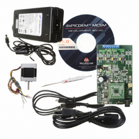
BOARD DEV DSPICDEM MCSM KIT
Manufacturer
Microchip Technology
Series
dsPIC™r
Datasheet
1.DM330022.pdf
(38 pages)
Specifications of DV330021
Main Purpose
Power Management, Motor Control
Embedded
*
Utilized Ic / Part
dsPIC33F
Primary Attributes
*
Secondary Attributes
*
Processor To Be Evaluated
dsPICDEM
Processor Series
dsPIC DSC
Interface Type
USB
Operating Supply Voltage
24 V
Silicon Manufacturer
Microchip
Silicon Core Number
DsPIC33F
Core Architecture
PIC
Core Sub-architecture
PIC33
Silicon Family Name
Piccolo
Lead Free Status / RoHS Status
Lead free / RoHS Compliant
Lead Free Status / RoHS Status
Lead free / RoHS Compliant, Lead free / RoHS Compliant
Available stocks
Company
Part Number
Manufacturer
Quantity
Price
Company:

Part Number:
DV330021
Manufacturer:
MICROCHIP
Quantity:
12 000


© 2009 Microchip Technology Inc.
3.3.1
The dsPICDEM MCSM Development Board receives the power for control circuits from
a +24V power supply. The 24V supply is always needed as it supplies 15V and 3.3V
necessary for the dsPIC DSC and for the interface between the dsPIC DSC and the
power stage. The power stage DC bus voltage can be connected to the development
board through the J6 or BP1-BP2 connectors.
3.3.2
By default, jumper J5 is short and jumper J7 is open, and the +24V input power supply
connected to J6 supplies both the control circuits and the DC bus voltage to the
development board. If jumper J7 is short and jumper J5 is open, the BP1-BP2
connectors supply the DC bus voltage to the development board power stage and J6
supplies the control circuits.
The 0-80V ADC power supply can be connected between BP1-BP2.
3.3.3
The development board uses an on-board PIC18 interface as a bridge between the
UART and the USB. The PIC18 UART pins are connected to the dsPIC33F devices on
different ports depending on the specific dsPIC33F device used. For the specific
devices that do not have remappable peripherals, additional UART RX/TX are
available on the device designated port for UART communication.
For dsPIC DSC devices that have an embedded USB port, populate R7, R8, R9 and
R10 with 0Ω resistors, and disable the PIC18 USB communication by removing R84
and R85.
3.3.4
The MPLAB ICD 3 and MPLAB REAL ICE Connector is an RJ11 female connector (J1)
that connects the MPLAB ICD 3 or MPLAB REAL ICE In-Circuit Debugger to the
dsPIC33F device for programming and debugging purposes. The PICkit 3 In-Circuit
Debugger/Programmer can be connected to the board using a 6-pin ICSP
connector (J2).
3.3.5
J3 is a 6-pin connector that connects the PICkit 3 In-Circuit Debugger/Programmer to
the PIC18F device. The development board uses the on-board PIC18 interface as a
bridge between the UART and USB. The PIC18F can be programmed for USB
communication.
3.3.6
The motor connector has eight terminals. Table 3-5 lists the functionality of each terminal.
TABLE 3-5:
Terminal Number
Input Power Connector (J6, BP1-BP2)
DC Bus Power Supply Connector (J5 and J7)
USB Interface (J4)
ICSP Connector for dsPIC DSC (J1/J2)
ICSP for PIC18 (J3)
Motor Connector (J8)
1
2
3
4
5
6
7
8
MOTOR CONNECTOR DETAILS
Designator
DC+
DC+
NC
NC
M1
M2
M3
M4
Not connected
Motor wire 1 (phase 1)
DC bus voltage
Motor wire 2 (phase 1)
Motor wire 3 (phase 2)
DC bus voltage
Motor wire 4 (phase 2)
Not connected
Description
DS70610A-page 25
Related parts for DV330021
Image
Part Number
Description
Manufacturer
Datasheet
Request
R

Part Number:
Description:
Manufacturer:
Microchip Technology Inc.
Datasheet:
Part Number:
Description:
Manufacturer:
Microchip Technology Inc.
Datasheet:
Part Number:
Description:
Manufacturer:
Microchip Technology Inc.
Datasheet:
Part Number:
Description:
Manufacturer:
Microchip Technology Inc.
Datasheet:
Part Number:
Description:
Manufacturer:
Microchip Technology Inc.
Datasheet:
Part Number:
Description:
Manufacturer:
Microchip Technology Inc.
Datasheet:
Part Number:
Description:
Manufacturer:
Microchip Technology Inc.
Datasheet:
Part Number:
Description:
Manufacturer:
Microchip Technology Inc.
Datasheet: