DV330021 Microchip Technology, DV330021 Datasheet - Page 27
DV330021
Manufacturer Part Number
DV330021
Description
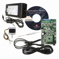
BOARD DEV DSPICDEM MCSM KIT
Manufacturer
Microchip Technology
Series
dsPIC™r
Datasheet
1.DM330022.pdf
(38 pages)
Specifications of DV330021
Main Purpose
Power Management, Motor Control
Embedded
*
Utilized Ic / Part
dsPIC33F
Primary Attributes
*
Secondary Attributes
*
Processor To Be Evaluated
dsPICDEM
Processor Series
dsPIC DSC
Interface Type
USB
Operating Supply Voltage
24 V
Silicon Manufacturer
Microchip
Silicon Core Number
DsPIC33F
Core Architecture
PIC
Core Sub-architecture
PIC33
Silicon Family Name
Piccolo
Lead Free Status / RoHS Status
Lead free / RoHS Compliant
Lead Free Status / RoHS Status
Lead free / RoHS Compliant, Lead free / RoHS Compliant
Available stocks
Company
Part Number
Manufacturer
Quantity
Price
Company:

Part Number:
DV330021
Manufacturer:
MICROCHIP
Quantity:
12 000


3.4
© 2009 Microchip Technology Inc.
USER INTERFACE HARDWARE
The dsPICDEM MCSM Development Board consists of the following push buttons,
LEDs and potentiometers:
• One push button
• One potentiometer
• Eight PWM LEDs
• One power-on status LED
• Two USB LEDs
• One Fault LED
• Device Reset push button
TABLE 3-7:
S1
POT1
RESET
D1
D2
D3-D10
D14
D15
Label
Push button; this push button is connected to a port pin. When momentarily
pressed, the switch connects the respective port pin to Ground.
10 kΩ potentiometer; it is connected to analog input pin.
Push button; this push button, when pressed, causes a device Reset.
USB communication indicator, which indicates the device has been detected.
USB bus indicator, which indicates that the device is connected to the USB bus.
LEDs, which indicate the PWM pin status. When an LED is ON, the respective
PWM pin is high.
Power-on status LED, which indicates the status of the
Fault LED; indicates an overcurrent.
INDICATORS AND HUMAN INTERFACES
Hardware Element Description
+
3.3V regulator.
DS70610A-page 27
Related parts for DV330021
Image
Part Number
Description
Manufacturer
Datasheet
Request
R

Part Number:
Description:
Manufacturer:
Microchip Technology Inc.
Datasheet:
Part Number:
Description:
Manufacturer:
Microchip Technology Inc.
Datasheet:
Part Number:
Description:
Manufacturer:
Microchip Technology Inc.
Datasheet:
Part Number:
Description:
Manufacturer:
Microchip Technology Inc.
Datasheet:
Part Number:
Description:
Manufacturer:
Microchip Technology Inc.
Datasheet:
Part Number:
Description:
Manufacturer:
Microchip Technology Inc.
Datasheet:
Part Number:
Description:
Manufacturer:
Microchip Technology Inc.
Datasheet:
Part Number:
Description:
Manufacturer:
Microchip Technology Inc.
Datasheet: