EK56 Cirrus Logic Inc, EK56 Datasheet - Page 2
EK56
Manufacturer Part Number
EK56
Description
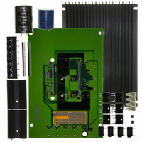
EVAL KIT FOR MSA240/MSA260
Manufacturer
Cirrus Logic Inc
Series
Apex Precision Power™r
Datasheet
1.EK56.pdf
(5 pages)
Specifications of EK56
Main Purpose
Power Management, H Bridge Driver (Internal FET)
Embedded
No
Utilized Ic / Part
MSA240, MSA260
Primary Attributes
3 V ~ 100 V Supply, 20A Output
Secondary Attributes
Assembly Required
Product
Amplifier Modules
Description/function
Audio Amplifiers
For Use With/related Products
MSA240KC, MSA260KC
Lead Free Status / RoHS Status
Contains lead / RoHS non-compliant
Other names
598-1469
EK56
EK56


EK56
ASSEMBLY CONT.
14. From the "DUT side" of the PCB snap the spacer- grom-
15. Apply a thin, uniform layer of thermal grease to the amplifier;
16. Attach the amplifier to the heatsink with 4-40x½’ male-
FIGURE 1: SCHEMATIC DIAGRAM
2
mets into the holes at the four corners of the PCB. Notice
that the holes are slightly rectangular and match the spacer-
grommet's long and short sides to the holes in the PCB.
a straight edge may be useful here. Position the amplifier
over the mounting holes in the heatsink. Firmly push the
amplifier onto the heatsink while slightly rotating the ampli-
fier back and forth, ending with the mounting holes of the
amplifier over the mounting holes in the heatsink.
female hex spacers (not supplied). These spacers serve
as alignment pins and aide in the assembly of the PCB to
the heatsink. Alternatively, use 4-40x¼’ machine screws
to mount the amplifier to the heatsink. Do not over-tighten
the spacers or screws as this provides no thermal benefit
and may break the hardware.
BNC
BJ1
BJ2
BJ3
BJ4
1
2
3
4
5
TS1
BREAD BOARDING TERMINALS
PWR
GND
PWR
GND
58
57
Isense B
56
1
55
2
R1
R3
54
3
NOTE: BREAD BOARDING ARRAY NOT SHOWN
NOTE: J1 AND J2 NORMALLY REQUIRED. SEE INSTRUCTIONS ABOVE
53
4
B OUT
C4
52
5
B OUT
51
6
R4
50
7
49
8
48
C5
9
47
0
P r o d u c t I n n o v a t i o n F r o m
+Vs
11
46
BANANA JACK
+Vs
R
12
45
RAMP2
13
44
17. Place the PCB assembly on the heatsink/amplifier assembly
18. Using #8 X 1" sheet metal screws (not provided) mount the
19. Hook up power and signals as necessary. The amplifier
14
43
R
Isense A
RAMP1
42
so that the hex spacers come through the aligning holes
near the corners of the amplifier location in the PCB. Care-
fully lower the PCB assembly until the pins of the amplifier
engage the cage jacks. Alternately, sight through the align-
ing holes in the PCB and match-up the PCB to the screws
used to mount the amplifier. In either case be sure the pins
of the amplifier are engaged with the cage jacks and then
continue pushing the PCB assembly in the area between
the amplifier’s pins until the four spacer grommets at the
four corners of the PCB touch the heatsink. At this point
the PCB should not be bowed.
PCB to the heat sink at the four spacer-grommets.
is now ready for testing.
5
16
41
C1
R2
17
40
C2 C3
18
+
39
A OUT
19
38
A OUT
RIM OF PLATED HOLE TIED TO SIG GND
HOLE IN PCB FOR BNC CONNECTOR
37
20
Rosc
21
36
22
35
J1
23
34
GND
SIG
24
33
+Vs
25
32
26
31
J2
27
30
SINGLE
POIINT
SIG GND
Vcc
Vcc
GND
28
29
EK56U
Related parts for EK56
Image
Part Number
Description
Manufacturer
Datasheet
Request
R

Part Number:
Description:
Development Kit
Manufacturer:
Cirrus Logic Inc
Datasheet:
Part Number:
Description:
Development Kit
Manufacturer:
Cirrus Logic Inc
Datasheet:


Part Number:
Description:
High-efficiency PFC + Fluorescent Lamp Driver Reference Design
Manufacturer:
Cirrus Logic Inc
Datasheet:
Part Number:
Description:
Development Kit
Manufacturer:
Cirrus Logic Inc
Datasheet:
Part Number:
Description:
Development Kit
Manufacturer:
Cirrus Logic Inc
Datasheet:

Part Number:
Description:
Development Kit
Manufacturer:
Cirrus Logic Inc
Datasheet:
Part Number:
Description:
Development Kit
Manufacturer:
Cirrus Logic Inc
Datasheet:
Part Number:
Description:
Development Kit
Manufacturer:
Cirrus Logic Inc
Datasheet:
Part Number:
Description:
Development Kit
Manufacturer:
Cirrus Logic Inc
Datasheet:

Part Number:
Description:
EVALUATION BOARD FOR CS8427
Manufacturer:
Cirrus Logic Inc
Datasheet:

Part Number:
Description:
BOARD EVAL FOR CS8416 RCVR
Manufacturer:
Cirrus Logic Inc
Datasheet:

Part Number:
Description:
EVALUATION BOARD FOR CS8420
Manufacturer:
Cirrus Logic Inc
Datasheet:

Part Number:
Description:
KIT DEVELOPMENT EP9315 ARM9
Manufacturer:
Cirrus Logic Inc
Datasheet:

Part Number:
Description:
KIT DEVELOPMENT EP9302 ARM9
Manufacturer:
Cirrus Logic Inc
Datasheet: