CDB3310 Cirrus Logic Inc, CDB3310 Datasheet - Page 8
CDB3310
Manufacturer Part Number
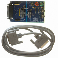
CDB3310
Description
BOARD EVAL FOR CS3310 COL CTRL
Manufacturer
Cirrus Logic Inc
Datasheet
1.CS3310-KSZ.pdf
(17 pages)
Specifications of CDB3310
Main Purpose
Audio, Volume Control
Embedded
No
Utilized Ic / Part
CS3310
Primary Attributes
Stereo Volume Control, 0.5 dB Step Size, Serial Control
Secondary Attributes
-95.5 dB Attenuation, +31.5 dB Gain, 0.001% THD+N, 116 dB Dynamic Range
Product
Audio Modules
Lead Free Status / RoHS Status
Contains lead / RoHS non-compliant
Lead Free Status / RoHS Status
Lead free / RoHS Compliant, Contains lead / RoHS non-compliant
Other names
598-1000


Changing the Analog Output Level
Care has been taken to ensure that there are no audible artifacts in the analog output signal dur-
ing volume control changes. The gain/attenuation changes of the CS3310 occur at zero cross-
ings to eliminate glitches during level transitions. The zero crossing for the left channel is the
voltage potential at the AGNDL pin; the voltage potential at the AGNDR pin defines the right
channel zero crossing.
A volume control change occurs after chip select latches the data in the volume control data reg-
ister and two zero crossings are detected. If two zero crossings are not detected within 18 ms of
the change in CS, the new volume setting is implemented. The zero crossing enable pin, ZCEN,
enables or disables the zero crossing detection function as well as the 18 ms time-out circuit.
Analog Inputs and Outputs
The maximum input level is limited by the common-mode voltage capabilities of the internal op-
amp. Signals approaching the analog supply voltages may be applied to the AIN pins if the inter-
nal attenuator limits the output signal to within 1.25 volts of the analog supply rails.
The outputs are capable of driving 600 Ω loads to within 1.25 volts of the analog supply rails and
are short circuit protected to 20 mA.
As with any adjustable gain stage the affects of a DC offset at the input must be considered. Ca-
pacitively coupling the analog inputs may be required to prevent “clicks and pops” which occur
with gain changes if an appreciable offset is present.
Source Impedance Requirements
The CS3310 requires a low source impedance to achieve maximum performance. The ESD pro-
tection diodes on the analog input pins are reversed biased during normal operation. A charac-
teristic of a reversed biased diode is a non-linear voltage dependent capacitance which can be
8
(Left or Right Channel) Gain or Attenuation (dB)
Input Code
00000010
00000001
00000000
11000000
11111110
11111111
Table 1. Input Code Definition
•
•
•
Software Mute
+31.5
+31.0
-95.0
-95.5
0
•
•
•
CS3310
DS82F1
Related parts for CDB3310
Image
Part Number
Description
Manufacturer
Datasheet
Request
R

Part Number:
Description:
Development Kit
Manufacturer:
Cirrus Logic Inc
Datasheet:
Part Number:
Description:
Development Kit
Manufacturer:
Cirrus Logic Inc
Datasheet:


Part Number:
Description:
High-efficiency PFC + Fluorescent Lamp Driver Reference Design
Manufacturer:
Cirrus Logic Inc
Datasheet:
Part Number:
Description:
Development Kit
Manufacturer:
Cirrus Logic Inc
Datasheet:
Part Number:
Description:
Development Kit
Manufacturer:
Cirrus Logic Inc
Datasheet:

Part Number:
Description:
Development Kit
Manufacturer:
Cirrus Logic Inc
Datasheet:
Part Number:
Description:
Development Kit
Manufacturer:
Cirrus Logic Inc
Datasheet:
Part Number:
Description:
Development Kit
Manufacturer:
Cirrus Logic Inc
Datasheet:
Part Number:
Description:
Development Kit
Manufacturer:
Cirrus Logic Inc
Datasheet:

Part Number:
Description:
EVALUATION BOARD FOR CS8427
Manufacturer:
Cirrus Logic Inc
Datasheet:

Part Number:
Description:
BOARD EVAL FOR CS8416 RCVR
Manufacturer:
Cirrus Logic Inc
Datasheet:

Part Number:
Description:
EVALUATION BOARD FOR CS8420
Manufacturer:
Cirrus Logic Inc
Datasheet:

Part Number:
Description:
KIT DEVELOPMENT EP9315 ARM9
Manufacturer:
Cirrus Logic Inc
Datasheet:

Part Number:
Description:
KIT DEVELOPMENT EP9302 ARM9
Manufacturer:
Cirrus Logic Inc
Datasheet: