EVL6562A-35WFLB STMicroelectronics, EVL6562A-35WFLB Datasheet - Page 2
EVL6562A-35WFLB
Manufacturer Part Number
EVL6562A-35WFLB
Description
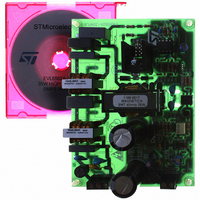
BOARD EVAL FOR L6562AX
Manufacturer
STMicroelectronics
Type
Power Factor Correctionr
Specifications of EVL6562A-35WFLB
Main Purpose
Power Management, Power Factor Correction
Embedded
No
Utilized Ic / Part
L6562A
Primary Attributes
35W, 48V Out, 90 ~ 265VAC In
Secondary Attributes
Transition Mode
Input Voltage
90 V to 265 V
Output Voltage
48 V
Board Size
120 mm x 82 mm
Product
Power Management Modules
Dimensions
120 mm x 82 mm
Lead Free Status / RoHS Status
Lead free / RoHS Compliant
For Use With/related Products
L6562A
Other names
497-8248
Available stocks
Company
Part Number
Manufacturer
Quantity
Price
Company:

Part Number:
EVL6562A-35WFLB
Manufacturer:
ON
Quantity:
100
Part Number:
EVL6562A-35WFLB
Manufacturer:
ST
Quantity:
20 000


Contents
Contents
1
2
3
4
5
6
7
8
9
10
2/26
Description . . . . . . . . . . . . . . . . . . . . . . . . . . . . . . . . . . . . . . . . . . . . . . . . . 3
Pin settings . . . . . . . . . . . . . . . . . . . . . . . . . . . . . . . . . . . . . . . . . . . . . . . . 4
2.1
2.2
Maximum ratings . . . . . . . . . . . . . . . . . . . . . . . . . . . . . . . . . . . . . . . . . . . . 5
Thermal data . . . . . . . . . . . . . . . . . . . . . . . . . . . . . . . . . . . . . . . . . . . . . . . 5
Electrical characteristics . . . . . . . . . . . . . . . . . . . . . . . . . . . . . . . . . . . . . 6
Typical electrical characteristic . . . . . . . . . . . . . . . . . . . . . . . . . . . . . . . . 9
Application information . . . . . . . . . . . . . . . . . . . . . . . . . . . . . . . . . . . . . 13
7.1
7.2
7.3
7.4
7.5
Application examples and ideas . . . . . . . . . . . . . . . . . . . . . . . . . . . . . . 18
Package mechanical data . . . . . . . . . . . . . . . . . . . . . . . . . . . . . . . . . . . . 22
Revision history . . . . . . . . . . . . . . . . . . . . . . . . . . . . . . . . . . . . . . . . . . . 25
Pin connection . . . . . . . . . . . . . . . . . . . . . . . . . . . . . . . . . . . . . . . . . . . . . . 4
Pin description . . . . . . . . . . . . . . . . . . . . . . . . . . . . . . . . . . . . . . . . . . . . . . 4
Overvoltage protection . . . . . . . . . . . . . . . . . . . . . . . . . . . . . . . . . . . . . . . 13
Disable function . . . . . . . . . . . . . . . . . . . . . . . . . . . . . . . . . . . . . . . . . . . . 14
THD optimizer circuit . . . . . . . . . . . . . . . . . . . . . . . . . . . . . . . . . . . . . . . . 14
Operating with no auxiliary winding on the boost inductor . . . . . . . . . . . . 16
Comparison between the L6562A and the L6562 . . . . . . . . . . . . . . . . . . 17
L6562A
Related parts for EVL6562A-35WFLB
Image
Part Number
Description
Manufacturer
Datasheet
Request
R

Part Number:
Description:
BOARD EVAL FOR L6562AX
Manufacturer:
STMicroelectronics
Datasheet:

Part Number:
Description:
BOARD EVAL FOR L6562A
Manufacturer:
STMicroelectronics
Datasheet:

Part Number:
Description:
EVALUATION MODULE L6562A
Manufacturer:
STMicroelectronics
Datasheet:

Part Number:
Description:
STMicroelectronics [RIPPLE-CARRY BINARY COUNTER/DIVIDERS]
Manufacturer:
STMicroelectronics
Datasheet:
Part Number:
Description:
STMicroelectronics [LIQUID-CRYSTAL DISPLAY DRIVERS]
Manufacturer:
STMicroelectronics
Datasheet:

Part Number:
Description:
BOARD EVAL FOR MEMS SENSORS
Manufacturer:
STMicroelectronics
Datasheet:
Part Number:
Description:
NPN TRANSISTOR POWER MODULE
Manufacturer:
STMicroelectronics
Datasheet:
Part Number:
Description:
TURBOSWITCH ULTRA-FAST HIGH VOLTAGE DIODE
Manufacturer:
STMicroelectronics
Datasheet:
Part Number:
Description:
Manufacturer:
STMicroelectronics
Datasheet:
Part Number:
Description:
DIODE / SCR MODULE
Manufacturer:
STMicroelectronics
Datasheet:
Part Number:
Description:
DIODE / SCR MODULE
Manufacturer:
STMicroelectronics
Datasheet:
Part Number:
Description:
Search -----> STE16N100
Manufacturer:
STMicroelectronics
Datasheet: