W682510DK Nuvoton Technology Corporation of America, W682510DK Datasheet - Page 8
W682510DK
Manufacturer Part Number
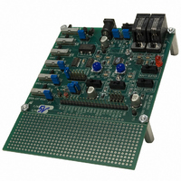
W682510DK
Description
KIT DEVELOPMENT FOR W682510
Manufacturer
Nuvoton Technology Corporation of America
Specifications of W682510DK
Main Purpose
Telecom, CODEC
Embedded
No
Utilized Ic / Part
W682510
Primary Attributes
Dual Voice Band PCM CODEC
Secondary Attributes
Parallel & Serial Modes, 2 RJ9 Handset Jacks
Lead Free Status / RoHS Status
Contains lead / RoHS non-compliant


7. FUNCTIONAL DESCRIPTION
W682510/W682310 is a single-rail, dual channel PCM CODEC for voiceband applications. The
CODEC complies with the specifications of the ITU-T G.712 recommendation. The CODEC includes
two complete μ-Law and A-Law companders. The μ-Law and A-Law companders are designed to
comply with the specifications of the ITU-T G.711 recommendation.
The block diagram in section 3 shows the main components of the W682510/W682310. The chip
consists of a PCM interface, which can process the data in parallel or serial formats. The PLL of the
chip provides the internal clock signals and synchronizes the CODEC sample rate with the external
frame sync frequency. The power-conditioning block provides the internal power supply for the digital
and the analog section, while the voltage reference block provides a precision analog ground voltage
for the analog signal processing.
The A-to-D path of the CODEC contains an analog input amplifier with externally configurable gain
setting (see application examples in section 11). The transmit amplifier output is the input to the
encoder section.
The output of the input amplifier is fed through a low-pass filter to prevent aliasing at the switched
capacitor 3.4 kHz low pass filter. The 3.4 kHz switched capacitor low pass filter prevents aliasing of
input signals above 4 kHz, due to the sampling at 8 kHz. The output of the 3.4 kHz low pass filter is
filtered by a high pass filter with a 200 Hz cut-off frequency. The filters are designed according to the
recommendations in the G.712 ITU-T specification. From the output of the high pass filter the signal is
digitized. The signal is converted into a compressed 8-bit digital representation with either μ-Law or A-
7.1. T
RANSMIT
DATA
DATA
DATA
DATA
DATA
DATA
DATA
DATA
DATA
T1
T1
R1
R1
R1
R2
R2
T1
T2
8
8
8
8
8
8
8
8
8
μ /A -
μ /A -
Control
Control
μ /A -
μ /A -
Control
Control
μ /A -
μ /A -
μ /A -
Control
Control
Control
μ /A -
μ /A -
Control
Control
P
FIGURE 7.1: THE W682510 AND W682310 SIGNAL PATH
8 bit μ /A - Law
8 bit μ /A - Law
8 bit μ /A - Law
8 bit μ /A - Law
8 bit μ /A - Law
8 bit μ /A - Law
8 bit μ /A - Law
8 bit μ /A - Law
8 bit μ /A - Law
ATH
DAC
DAC
DAC
DAC
DAC
ADC
ADC
ADC
ADC
f
f
f
f
C
C
High Pass
High Pass
C
C
High Pass
High Pass
= 200 Hz
= 200 Hz
= 200 Hz
= 200 Hz
Filter
Filter
Filter
Filter
- 8 -
Anti- Aliasing
Anti-Aliasin
Anti-
Anti-Aliasin
Anti-Aliasing
Anti-
f
f
f
f
f
f
f
f
f
f
f
f
f
C
C
C
C
C
C
C
C
C
C
C
C
C
Smoothing
Smoothing
Smoothing
Smoothing
Smoothing
Smoothing
Smoothing
= 3400 Hz
= 3400 Hz
= 3400 Hz
= 3400 Hz
Filter 1a
Filter 1a
Filter 1a
Filter 1a
= 3400 Hz
= 3400 Hz
= 3400 Hz
Filter 2a
Filter 2a
Filter 2a
= 3400 Hz
= 3400 Hz
= 3400 Hz
Filter 1a
Filter 1a
Filter 1a
= 3400 Hz
= 3400 Hz
= 3400 Hz
Filter 2a
Filter 2a
Filter 2a
Anti- Aliasing
Anti-Aliasin
Anti-
Anti-Aliasin
Anti- Aliasing
Anti-
Smoothing
Smoothing
Smoothing
Smoothing
Smoothing
Smoothing
Smoothing
Filter 1b
Filter 1b
Filter 1b
Filter 1b
Filter 2b
Filter 2b
Filter 2b
Filter 1b
Filter 1b
Filter 1b
Filter 2b
Filter 2b
Filter 2b
W682510/W682310
+
+
+
+
+
-
-
-
-
-
-
-
-
-
+
+
+
+
Buffer1
Buffer1
Buffer1
Av=1
Av=1
Av=1
Buffer2
Buffer2
Av=1
Av=1
RO1
RO1
RO1
RO2
RO2
AI1
AI1
AI1
AI2
AI2
AI2
AO1 -
AO1 -
AO2 -
AO2 -
Related parts for W682510DK
Image
Part Number
Description
Manufacturer
Datasheet
Request
R

Part Number:
Description:
Manufacturer:
Nuvoton Technology Corporation of America
Datasheet:
Part Number:
Description:
Manufacturer:
Nuvoton Technology Corporation of America
Datasheet:
Part Number:
Description:
Manufacturer:
Nuvoton Technology Corporation of America
Datasheet:
Part Number:
Description:
Manufacturer:
Nuvoton Technology Corporation of America
Datasheet:
Part Number:
Description:
Manufacturer:
Nuvoton Technology Corporation of America
Datasheet:
Part Number:
Description:
Manufacturer:
Nuvoton Technology Corporation of America
Datasheet:
Part Number:
Description:
Manufacturer:
Nuvoton Technology Corporation of America
Datasheet: