ISD-ES15100_USB Nuvoton Technology Corporation of America, ISD-ES15100_USB Datasheet - Page 19
ISD-ES15100_USB
Manufacturer Part Number
ISD-ES15100_USB
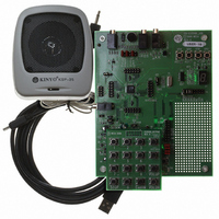
Description
BOARD EVALUATION USB FOR I15100
Manufacturer
Nuvoton Technology Corporation of America
Series
ChipCorder®r
Specifications of ISD-ES15100_USB
Main Purpose
Audio, Voice Record/Playback
Embedded
No
Utilized Ic / Part
ISD15102, 04, 08, 16, 32
Primary Attributes
ASIC, 2 ~ 16 Minutes, Up to 48kHz, Class D Amp, Line/Digital/Mic Input
Secondary Attributes
Graphic User Interface
Lead Free Status / RoHS Status
Not applicable / Not applicable


3.1
Figure 3-2 below is the ISD15100 EV board. On the right hand side is the ISD15U110 (A), our ISD
USB1.1 controller especially designed for ChipCorder ISD15100 family. In the middle is the ISD15108
(B), 8-minute duration based on 8 kHz & 4-bit ADPCM. On the left hand side are analog circuitry and
connectors for recording and playback. Upper left corner is a 7-segment display (C) controlled by four
GPIO pins of ISD15108 (B). Upper right corner is a hole-array (D) for users’ prototyping.
The EV board can be operated standalone or controlled by VPE. To operate standalone, make sure
the VPE project is properly downloaded into the board; the playback path setting should be done in
users’ PU macro (VM1). Attach the keypad onto HJ1 (E) and insert 3 AAA batteries into the battery
holder underneath the board. The USB controller will power-on and reset the ISD15108 in 3 seconds.
Press the buttons to:
For example, to execute VM 25, do the following:
Around the ISD15108 (B) are four pin-headers (F) used for adaptation of daughter cards. To attach
any daughter card onto the EV board:
On board there are a 4MHz crystal and an 80k-ohm resistor for clock setting (I). Users use jumper
J12 to select the clock source:
3.
•
•
•
•
•
•
•
•
•
•
•
•
Evaluation System
EV Board Overview
ExeVM: power-up the on-board ISD15108 or send ExeVM command.
STOP: send STOP command and clear index.
0 ~ 9: indexes for executing VM.
VOLUP/VOLDN: increase/decrease volume.
Press ExeVM. ISD15108 will be powered-up.
Press 2. Users shall see ‘2’ displayed on the 7-segment display (C).
Press 5. Users shall see ‘5’ displayed on the 7-segment display (C).
Press ExeVM to execute VM 25.
Make sure the on-board ISD15108 has been chip-erased.
Remove jumpers J17 SSB (G) and J21 RDY_BSYB (H).
Attach the daughter card via the four pin-headers (F).
Internal oscillator with internal resistor:
o
o
USB firmware checks if the ISD15108 is powered up. If not, send power-up
command; if yes, send ExeVM command.
It doesn’t matter how the jumper is setting.
Figure 3-1 Keypad for Standalone
Publication Release Date: May 21, 2008
PRELIMINARY
Revision 151.003
19
Related parts for ISD-ES15100_USB
Image
Part Number
Description
Manufacturer
Datasheet
Request
R

Part Number:
Description:
Manufacturer:
Nuvoton Technology Corporation of America
Datasheet:
Part Number:
Description:
Manufacturer:
Nuvoton Technology Corporation of America
Datasheet:
Part Number:
Description:
Manufacturer:
Nuvoton Technology Corporation of America
Datasheet:
Part Number:
Description:
Manufacturer:
Nuvoton Technology Corporation of America
Datasheet:
Part Number:
Description:
Manufacturer:
Nuvoton Technology Corporation of America
Datasheet:
Part Number:
Description:
Manufacturer:
Nuvoton Technology Corporation of America
Datasheet:
Part Number:
Description:
Manufacturer:
Nuvoton Technology Corporation of America
Datasheet: