ISD-ES15100_USB Nuvoton Technology Corporation of America, ISD-ES15100_USB Datasheet - Page 7
ISD-ES15100_USB
Manufacturer Part Number
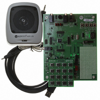
ISD-ES15100_USB
Description
BOARD EVALUATION USB FOR I15100
Manufacturer
Nuvoton Technology Corporation of America
Series
ChipCorder®r
Specifications of ISD-ES15100_USB
Main Purpose
Audio, Voice Record/Playback
Embedded
No
Utilized Ic / Part
ISD15102, 04, 08, 16, 32
Primary Attributes
ASIC, 2 ~ 16 Minutes, Up to 48kHz, Class D Amp, Line/Digital/Mic Input
Secondary Attributes
Graphic User Interface
Lead Free Status / RoHS Status
Not applicable / Not applicable


2.2
Users choose the device (A) and clock source (B) on the ‘Device/Clocks’ screen. The Memory Size
selection (A) is for VPE to calculate and show the memory usage (C). If the EV board is present, VPE
automatically sets the device (A) to reflect the hardware.
VPE provides several most common clock settings. For every clock setting, seven sub-sampling rates
are available for VP compression as shown in Table 2-1. Clock configuration is part of the VP
compression, so whenever users change the clock configuration, they have to ‘Re-compress All’ VPs
(button on ‘Voice Prompt’ screen). The one-byte CLK_CFG (D) is for clock setting in voice macro. If
the clock settings that VPE provides do not fit the users’ needs, users may switch to the advanced
view (E).
Please note that the clock setting (B) here is ONLY for VP compression; it is for making a project.
Users also need to set the clock for the ISD chip by either setting it in their POI/PU macros or by
sending SPI commands after the chip powers up.
The default clock setting for ISD chip when POI/PU:
In the example project, we choose ISD15102 (A) and set the clock to 4.096 MHz Crystal (B).
•
•
•
•
•
BinFiles: where the compressed VPs are stored.
WavFiles: where the re-sampled and de-compressed VPs are stored.
WavSrc: where wave sources of VPs are stored.
Device/Clocks
If the POI/PU macro is empty:
If the POI/PU macro exists, but users do not set clock in it:
o
o
Clock sets to 0x34, which is internal oscillator with internal resistor.
Clock sets to 0x00, which bypasses the PLL.
Sampled
Sub-
ratio
8
6
Figure 2-4 Memory Usage Indicator
Figure 2-3 Device/Clocks Setting
Master Sample Rate Fs (kHz)
5.333
32
4
5.5125
44.1
7.35
Publication Release Date: May 21, 2008
48
6
8
PRELIMINARY
Revision 151.003
7
Related parts for ISD-ES15100_USB
Image
Part Number
Description
Manufacturer
Datasheet
Request
R

Part Number:
Description:
Manufacturer:
Nuvoton Technology Corporation of America
Datasheet:
Part Number:
Description:
Manufacturer:
Nuvoton Technology Corporation of America
Datasheet:
Part Number:
Description:
Manufacturer:
Nuvoton Technology Corporation of America
Datasheet:
Part Number:
Description:
Manufacturer:
Nuvoton Technology Corporation of America
Datasheet:
Part Number:
Description:
Manufacturer:
Nuvoton Technology Corporation of America
Datasheet:
Part Number:
Description:
Manufacturer:
Nuvoton Technology Corporation of America
Datasheet:
Part Number:
Description:
Manufacturer:
Nuvoton Technology Corporation of America
Datasheet: