SPUSI2/NOPB National Semiconductor, SPUSI2/NOPB Datasheet - Page 10
SPUSI2/NOPB
Manufacturer Part Number
SPUSI2/NOPB
Description
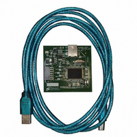
BOARD EVAL DATA CAPTURE BOARD
Manufacturer
National Semiconductor
Specifications of SPUSI2/NOPB
Main Purpose
Interface, Data Capture
Embedded
Yes, MCU, 8-Bit
Utilized Ic / Part
WEBENCH® Sensor Designer Boards
Primary Attributes
USB Interface Dongle II
Secondary Attributes
SPI Interface
Lead Free Status / RoHS Status
Lead free / RoHS Compliant
Other names
SPUSI2
Available stocks
Company
Part Number
Manufacturer
Quantity
Price
Company:

Part Number:
SPUSI2/NOPB
Manufacturer:
National Semiconductor
Quantity:
135


4.1.5 Channel State Indicator Colors.
channel state. A gray indicator corresponds to a disabled or absent channel. A
green indicator corresponds to a channel with valid measurements.
indicator corresponds to a channel with invalid measurements that have been
persistent for more than a programmed acceptable level, i.e. they are
continuously outside the valid minimum and maximum values. This generally
indicates a disconnected channel and the channel value field will eventually be
cleared to avoid confusion. An orange indicator corresponds to invalid values
that have not been held.
communication with the hardware and can also occur if the application is running
on a busy system and becomes starved for computational resources.
4.2 Control Buttons.
control buttons below the channel panes. The Start/Stop Measurements and
Record buttons correspond to all channels simultaneously. The Calibrate button
calibrates the measurements for the current channel selected in the board
configuration.
4.2.1 Start/Stop Measurements.
measurements on all enabled channels simultaneously. The MEASURE button
is highlighted when the cursor is held above it and changes to STOP when
measurements are being made. Starting measurements when no channels are
enabled is not allowed.
4.2.2 Record Measurements.
text log file. The values are not written until the recording is completed and the
button is automatically reset to its initial state to indicate that another recording
can be made. The SCP software is set to record 100 samples each time the
RECORD button is selected.
The color indicator in the lower center of the channel pane indicates the
The lower portion of the Sensor Signal Path Control Panel contains three
The right button is the MEASURE button. It is used to start and stop the
The left button is used to record channel codes and measurements in a
Figure 4-2: Channel State Indicator Colors.
Figure 4-3: Start/Stop Measurements.
Figure 4-4: Record Measurements.
Invalid values are generally caused by a loss of
A red
Related parts for SPUSI2/NOPB
Image
Part Number
Description
Manufacturer
Datasheet
Request
R

Part Number:
Description:
National Semiconductor [8-Bit D/A Converter]
Manufacturer:
National Semiconductor
Datasheet:
Part Number:
Description:
National Semiconductor [Media Coprocessor]
Manufacturer:
National Semiconductor
Datasheet:
Part Number:
Description:
Digitally Controlled Tone and Volume Circuit with Stereo Audio Power Amplifier, Microphone Preamp Stage and National 3D Sound
Manufacturer:
National Semiconductor
Datasheet:
Part Number:
Description:
Digitally Controlled Tone and Volume Circuit with Stereo Audio Power Amplifier, Microphone Preamp Stage and National 3D Sound
Manufacturer:
National Semiconductor
Datasheet:
Part Number:
Description:
AC97 Rev 2 Codec with Sample Rate Conversion and National 3D Sound
Manufacturer:
National Semiconductor
Part Number:
Description:
Manufacturer:
National Semiconductor
Datasheet:
Part Number:
Description:
Manufacturer:
National Semiconductor
Datasheet:
Part Number:
Description:
General Purpose, Low Voltage, Low Power, Rail-to-Rail Output Operational Amplifiers
Manufacturer:
National Semiconductor
Datasheet:
Part Number:
Description:
8-bit 20 MSPS flash A/D converter.
Manufacturer:
National Semiconductor
Datasheet:
Part Number:
Description:
Low Noise Quad Operational Amplifier
Manufacturer:
National Semiconductor
Datasheet:
Part Number:
Description:
Quad Differential Line Receivers
Manufacturer:
National Semiconductor
Datasheet:
Part Number:
Description:
Quad High Speed Trapezoidal? Bus Transceiver
Manufacturer:
National Semiconductor
Datasheet:
Part Number:
Description:
Dual Line Receiver
Manufacturer:
National Semiconductor
Datasheet:
Part Number:
Description:
TTL to 10k ECL Level Translator with Latch
Manufacturer:
National Semiconductor
Datasheet: