SPUSI2/NOPB National Semiconductor, SPUSI2/NOPB Datasheet - Page 5
SPUSI2/NOPB
Manufacturer Part Number
SPUSI2/NOPB
Description
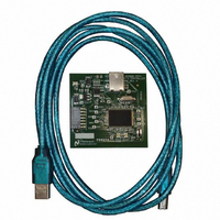
BOARD EVAL DATA CAPTURE BOARD
Manufacturer
National Semiconductor
Specifications of SPUSI2/NOPB
Main Purpose
Interface, Data Capture
Embedded
Yes, MCU, 8-Bit
Utilized Ic / Part
WEBENCH® Sensor Designer Boards
Primary Attributes
USB Interface Dongle II
Secondary Attributes
SPI Interface
Lead Free Status / RoHS Status
Lead free / RoHS Compliant
Other names
SPUSI2
Available stocks
Company
Part Number
Manufacturer
Quantity
Price
Company:

Part Number:
SPUSI2/NOPB
Manufacturer:
National Semiconductor
Quantity:
135


corresponding to the channel selected in the Channel # window in the top middle
of the control panel.
measurements for all enabled channels.
3 Board Configuration.
actually channel specific and consists of many parameters that change across
the various boards and channels. The software contains a configuration panel
which is discussed separately. The individual board documentation explains
these parameters in more detail.
3.1 Channels.
to the channel panes in the lower part of the control panel. Generally the board
channels are programmed to correspond to their respective pane channels 1
through 4.
values of the different stages of the signal path for a respective physical channel.
For example, in the case of the SP1202S01RB, pane 1 is used to display the
Sensor output value in terms of its own sensor units, pane 2 displays the
sensor’s output voltage in terms of volts, pane 3 displays the ADC input voltage
level, and pane 4 displays the ADC’s output code value (refer to Figure 3-2:
SP1202S01RB). All of these measurements are referenced to the ADC output
value of physical channel 1.
3.1.1 Channel Pane Selection.
top left corner of the panel, or by clicking in the channel panel. Note that the
channel selection options may be limited to configurable channels on the board.
The top portion of the panel provides access to the configuration
The board Configure menu option at the top of the Control Panel is
Each board consists of one or more physical channels which are mapped
A channel is selected by clicking on it in the channel id list window in the
However, certain boards may use multiple panes to display the
Figure 3-3: Channel Selection list of present channels.
Figure 3-1: Channel Specific Board Configuration.
The lower portion of the panel provides the sensor
Related parts for SPUSI2/NOPB
Image
Part Number
Description
Manufacturer
Datasheet
Request
R

Part Number:
Description:
National Semiconductor [8-Bit D/A Converter]
Manufacturer:
National Semiconductor
Datasheet:
Part Number:
Description:
National Semiconductor [Media Coprocessor]
Manufacturer:
National Semiconductor
Datasheet:
Part Number:
Description:
Digitally Controlled Tone and Volume Circuit with Stereo Audio Power Amplifier, Microphone Preamp Stage and National 3D Sound
Manufacturer:
National Semiconductor
Datasheet:
Part Number:
Description:
Digitally Controlled Tone and Volume Circuit with Stereo Audio Power Amplifier, Microphone Preamp Stage and National 3D Sound
Manufacturer:
National Semiconductor
Datasheet:
Part Number:
Description:
AC97 Rev 2 Codec with Sample Rate Conversion and National 3D Sound
Manufacturer:
National Semiconductor
Part Number:
Description:
Manufacturer:
National Semiconductor
Datasheet:
Part Number:
Description:
Manufacturer:
National Semiconductor
Datasheet:
Part Number:
Description:
General Purpose, Low Voltage, Low Power, Rail-to-Rail Output Operational Amplifiers
Manufacturer:
National Semiconductor
Datasheet:
Part Number:
Description:
8-bit 20 MSPS flash A/D converter.
Manufacturer:
National Semiconductor
Datasheet:
Part Number:
Description:
Low Noise Quad Operational Amplifier
Manufacturer:
National Semiconductor
Datasheet:
Part Number:
Description:
Quad Differential Line Receivers
Manufacturer:
National Semiconductor
Datasheet:
Part Number:
Description:
Quad High Speed Trapezoidal? Bus Transceiver
Manufacturer:
National Semiconductor
Datasheet:
Part Number:
Description:
Dual Line Receiver
Manufacturer:
National Semiconductor
Datasheet:
Part Number:
Description:
TTL to 10k ECL Level Translator with Latch
Manufacturer:
National Semiconductor
Datasheet: