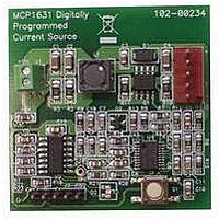
MCP1631RD-MCC1 Microchip Technology, MCP1631RD-MCC1 Datasheet - Page 13

MCP1631RD-MCC1
Manufacturer Part Number
MCP1631RD-MCC1
Description
REFERENCE DESIGN FOR MCP1631HV
Manufacturer
Microchip Technology
Type
Battery Managementr
Datasheets
1.MCP1631VHVT-330EST.pdf
(34 pages)
2.MCP1631HV-330EST.pdf
(54 pages)
3.MCP1631RD-MCC2.pdf
(20 pages)
4.MCP1631RD-MCC2.pdf
(328 pages)
5.MCP1631RD-MCC1.pdf
(28 pages)
Specifications of MCP1631RD-MCC1
Main Purpose
Power Management, Battery Charger
Embedded
Yes, MCU, 8-Bit
Utilized Ic / Part
MCP1631HV, PIC16F883
Primary Attributes
1 ~ 2 Cell- Li-Ion, 1 ~ 4 Cell- NiCd/NiMH
Secondary Attributes
Status LEDs
Supported Devices
MCP1631HV, PIC16F883 Device Type
Tool / Board Applications
Power Management-Battery Management
Development Tool Type
Reference Design
Input Voltage
5.5 V to 16 V
Product
Power Management Modules
Mcu Supported Families
MCP1631HV/PIC16F883 Family
Silicon Manufacturer
Microchip
Silicon Core Number
MCP1631HV
Kit Application Type
Reference Design
Application Sub Type
Battery Charger
Kit Contents
Board Only
Lead Free Status / RoHS Status
Lead free / RoHS Compliant
For Use With/related Products
MCP1631HV, PIC16F883
Lead Free Status / RoHS Status
Lead free / RoHS Compliant
© 2007 Microchip Technology Inc.
FIGURE 2-2:
NiMH/NiCd.
2.3.1
2.3.1.1
1. Apply the input voltage to the input terminal block, J1. The input voltage source
2. Connect the positive side of the input source (+) to pin 1 of J1. Connect the
should be limited to the 0V to +16V range. For nominal operation the input
voltage should be between +5.3V and +16V.
negative or return side (-) of the input source to pin 2 of J1. Refer to Figure 2-3.
Power Input and Output Connection
POWERING THE MCP1631HV MULTI-CHEMISTRY BATTERY
CHARGER
5.0
4.0
3.0
2.0
1.0
0.0
MCP1631HV Multi-Chemistry Battery Charger Charge profile,
3 Cell 2,000 mA-hr NiMH Batteries
Time (Minutes)
Installation and Operation
DS51697A-page 9
60
50
40
30
20
10
0


