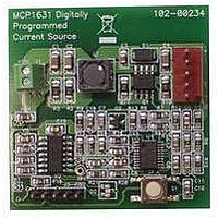
MCP1631RD-MCC1 Microchip Technology, MCP1631RD-MCC1 Datasheet - Page 16

MCP1631RD-MCC1
Manufacturer Part Number
MCP1631RD-MCC1
Description
REFERENCE DESIGN FOR MCP1631HV
Manufacturer
Microchip Technology
Type
Battery Managementr
Datasheets
1.MCP1631VHVT-330EST.pdf
(34 pages)
2.MCP1631HV-330EST.pdf
(54 pages)
3.MCP1631RD-MCC2.pdf
(20 pages)
4.MCP1631RD-MCC2.pdf
(328 pages)
5.MCP1631RD-MCC1.pdf
(28 pages)
Specifications of MCP1631RD-MCC1
Main Purpose
Power Management, Battery Charger
Embedded
Yes, MCU, 8-Bit
Utilized Ic / Part
MCP1631HV, PIC16F883
Primary Attributes
1 ~ 2 Cell- Li-Ion, 1 ~ 4 Cell- NiCd/NiMH
Secondary Attributes
Status LEDs
Supported Devices
MCP1631HV, PIC16F883 Device Type
Tool / Board Applications
Power Management-Battery Management
Development Tool Type
Reference Design
Input Voltage
5.5 V to 16 V
Product
Power Management Modules
Mcu Supported Families
MCP1631HV/PIC16F883 Family
Silicon Manufacturer
Microchip
Silicon Core Number
MCP1631HV
Kit Application Type
Reference Design
Application Sub Type
Battery Charger
Kit Contents
Board Only
Lead Free Status / RoHS Status
Lead free / RoHS Compliant
For Use With/related Products
MCP1631HV, PIC16F883
Lead Free Status / RoHS Status
Lead free / RoHS Compliant
MCP1631 Multi-Chemistry Battery Charger Reference Design
DS51697A-page 12
2.3.1.4
1. The MCP1631HV Multi-Chemistry Battery Charger has an LED to indicate
TABLE 2-1:
2.3.1.5
• Li-Ion
• NiMH/NiCd
2.3.1.6
Header J3 is provided for in-system circuit programming.
Programming
Qualification
Preconditioning
Constant Current Fast Charge
Top Off Charge
Charge Complete
Safety Timer Fault
Cell Temperature Invalid
Battery Disconnected
Input Power Removed
- Qualification: Precharge at 200 mA for V
- Constant Current = 2A for 1 Cell, 1A for 2 Cell
- Constant Voltage = 4.20V, Calibrated at board final test
- Charge Termination = 140 mA for 1 Cell and 2 Cell
- Overvoltage Detection, once detected, attempt to restart charge cycle 5 times,
- Qualification: Precharge at 200 mA for V
- Constant Current = 1.5A for 1 Cell to 4 Cell
- Terminate Fast Charge for -dV/dT or +dT/dt
- Timed 50 mA top off charge for 1 hour
- Overvoltage Detection, once detected, attempt to restart charge cycle 5 times,
charge status or fault status. Table 2-1 represents the state of the Satus LED dur-
ing various states of the charge cycle.
if overvoltage is persistant, terminate attemtps and flash STATUS LED.
if overvoltage is persistant, terminate attemtps and flash STATUS LED.
Charge Cycle State
STATUS LED
CHARGE PROFILE
PROGRAMMING
STATUS OUTPUT
Flashing (Fast)
OFF
ON
ON
ON
OFF
Flashing (2 Hertz)
Flashing (2 Hertz)
Flashing ( 2 Hertz)
OFF
CELL
CELL
LED
< 3.0V
< 0.9V
© 2007 Microchip Technology Inc.


