MCP3909RD-1PH1 Microchip Technology, MCP3909RD-1PH1 Datasheet - Page 23
MCP3909RD-1PH1
Manufacturer Part Number
MCP3909RD-1PH1
Description
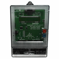
BOARD DES MCP3909 ENERGY METER
Manufacturer
Microchip Technology
Datasheets
1.MCP3909T-ISS.pdf
(44 pages)
2.MCP3909RD-1PH1.pdf
(60 pages)
3.MCP3909RD-1PH1.pdf
(6 pages)
Specifications of MCP3909RD-1PH1
Main Purpose
Power Management, Energy/Power Meter
Embedded
Yes, MCU, 8-Bit
Utilized Ic / Part
MCP3909, PIC18F85J90
Primary Attributes
Single Phase Shunt Energy Meter
Secondary Attributes
16 Bit ADC
Ic Function
Single Phase Energy Measurement IC
Supply Voltage Range
4.5V To 5.5V
Operating Temperature Range
-40°C To +85°C
Digital Ic Case Style
SSOP
No. Of Pins
24
Interface Type
SPI
Lead Free Status / RoHS Status
Contains lead / RoHS non-compliant
Lead Free Status / RoHS Status
Contains lead / RoHS non-compliant


3.4.4
3.4.5
3.4.6
3.4.7
© 2009 Microchip Technology Inc.
LINE_CYC
LINE_CYC_CNT
PHA_W_RAW
PHA_W
REGISTER 3-4:
Number of line cycles as a power of two. A setting of 0 indicates 2
setting of 1 is 2 line cycles (2
which is 256 line cycles. When written, this register will not take effect until the previous
number of line cycles has been acquired.
REGISTER 3-5:
This register counts from 0 and finishes at 2
LINE_CYC represents the value in the LINE_CYC register.
REGISTER 3-6:
These registers are the raw phase A active power as it represents the sum of each
phase y current A/D value times phase y voltage A/D value results over LINE_CYC line
cycles (each line cycle has 128 results). Each current times voltage multiplication
results in a 32-bit word. There are up to 256 line cycles with each line cycle being
128 results and each result being 32-bit. Thus, a 48-bit register is needed. This is the
register to be read during calibration for calculating the offset and gain values
associated with active phase y power, PHy_W_OFF, PHy_W_GAIN, and
PHy_W_GLSB. These registers are overwritten every line cycle, however if calibration
is enabled, updates will stop once LINE_CYC line cycles have elapsed.
REGISTER 3-7:
These registers are the value for phase A active power. The goal of calibration is to get
these registers values to equal X 0.1 mW/LSB. When displaying the active power for
phase y, simply display the value in these registers with the decimal point one digit in
from the right, in milli-watts. (Note this decimal point location, or LSB resolution of
0.1 mW, is specific for the 5(10)A, 220V rating that this meter is designed for). This
register is overwritten every LINE_CYC line cycles (written only once if calibration is
enabled).
LINE_CYC_CNT
LINE_CYC
Name
PHA_W_RAW
Name
PHA_W
Name
Name
Calculation and Register Description
Bits
16
Bits
LINE_CYC REGISTER
LINE_CYC_CNT REGISTER
PHA_W_RAW REGISTER
PHA_W REGISTER
16
Bits
Bits
48
32
Address
0x00A
1
Address
Address
Address
), a setting of 2 is 4 lines cycles (2
0x00C
0x064
0x076
R/W
Cof
Cof
Cof
Cof
R
R
R
(LINE_CYC)
-1 and then re-starts at 0, where
2
), up to a setting of 8
0
or 1 line cycle. A
DS51884A-page 23
Related parts for MCP3909RD-1PH1
Image
Part Number
Description
Manufacturer
Datasheet
Request
R

Part Number:
Description:
REF DESIGN FOR MCP3909 W/18F2520
Manufacturer:
Microchip Technology
Datasheet:

Part Number:
Description:
REF DESIGN MCP3909 3PH ENGY MTR
Manufacturer:
Microchip Technology
Datasheet:

Part Number:
Description:
Manufacturer:
Microchip Technology Inc.
Datasheet:
Part Number:
Description:
Manufacturer:
Microchip Technology Inc.
Datasheet:
Part Number:
Description:
Manufacturer:
Microchip Technology Inc.
Datasheet:
Part Number:
Description:
Manufacturer:
Microchip Technology Inc.
Datasheet:
Part Number:
Description:
Manufacturer:
Microchip Technology Inc.
Datasheet:
Part Number:
Description:
Manufacturer:
Microchip Technology Inc.
Datasheet:
Part Number:
Description:
Manufacturer:
Microchip Technology Inc.
Datasheet:
Part Number:
Description:
Manufacturer:
Microchip Technology Inc.
Datasheet: