ATA6823-DK Atmel, ATA6823-DK Datasheet - Page 19
ATA6823-DK
Manufacturer Part Number
ATA6823-DK
Description
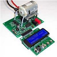
BOARD EVALUATION FOR ATA6823
Manufacturer
Atmel
Type
PWM Controllersr
Specifications of ATA6823-DK
Main Purpose
Power Management, Motor Control
Embedded
No
Utilized Ic / Part
ATA6823
Primary Attributes
Brush DC Motors, 8 ~ 18V, LIN Interface, Watchdog, 5V Regulator
Secondary Attributes
Cross Conduction, Under/Over Voltage, Short Circuit, & Temperature Protection
Input Voltage
8 V to 18 V
Product
Power Management Modules
Lead Free Status / RoHS Status
Contains lead / RoHS non-compliant
For Use With/related Products
ATA6823


8. Electrical Characteristics (Continued)
All parameters given are valid for V
4856K–AUTO–01/11
* Type: A = 100% tested, B = 100% correlation tested, C = Characterized on samples, D = Design parameter
Notes:
3.15 Open window
3.16
3.17
4.8a Pull up resistor to VS
4.8b
4.10
4.11
No. Parameters
4.1
4.2
4.3
4.4
4.5
4.6
4.7
4.9
4
Output low-voltage of
/RESET
Internal pull-up resistor at
pin /RESET
LIN Transceiver, 7V
Low-level output current
High-level output current
Driver recessive output
voltage
Driver dominant voltage
V
Driver dominant voltage
V
Driver dominant voltage
V
Driver dominant voltage
V
Capacitance on LIN pin to
GND
Current limitation
Input leakage current at
the receiver including
pull-up resistor as
specified
Leakage current LIN
recessive
BUSdom_DRV_LoSUP
BUSdom_DRV_HiSUP
BUSdom_DRV_LoSUP
BUSdom_DRV_HiSUP
1. EN, DIR, PWM = high
2. The use of X7R material is recommended
3. For higher values, stability at zero load is not guaranteed
4. Tested during qualification only
5. Value depends on T
6. Tested during characterization only
7. Supplied by charge pump
8. See section
9. Voltage between source-drain of external switching transistors in active case
10. The short-circuit message will never be generated for switch-on time < t
“Cross Conduction Time”
V
VBAT
OSC
THUV
Test Conditions
(5)
At I
Normal mode;
V
Normal mode; V
V
R
V
R
V
R
V
R
V
R
Serial diode required
V
Input leakage current
driver off
V
V
Driver off
7V < V
7V < V
V
; function tested with digital test pattern
LIN
RX
VBAT
VBAT
VBAT
VBAT
BUS
BUS
VBAT
BUS
LOAD
load
load
load
load
OLRES
18V
= V
= 0V, V
= 500
= 500
= 1000
= 1000
= V
= 0V
= V
V
= 7.0V
= 18V
= 7.0V
= 18V
= 12V
= 1000 to VBAT
VBAT
BUS
VBAT
CC
VBAT_max
VBAT
= 1mA
– 0.4V
< 18V
< 18V
RX
V
= 0.4V
THOV
LIN
= V
and for –40°C
VBAT
Pin
13
13
8
6
5
5
8
8
8
8
8
8
8
8
8
ambient 125°C unless stated otherwise.
I
V
I
BUS_PAS_dom
V
BUS_PAS_rec
V
Symbol
V
_HiSUP_1k_
I
R
V
V
_LoSUP_1k
BUSrecdrv
BUS_LIM
IH
IL
_LoSUP
_HiSUP
R
C
OLRES
PURES
t2
RXD
RXD
LIN
LIN
sc
0.9
V
Min.
0.6
0.8
VBAT
20
50
–1
5
2
1
780
T
Typ.
10
Atmel ATA6823
OSC
Max.
200
0.4
1.2
15
47
20
20
2
Unit
mA
mA
mA
mA
k
k
pF
µA
V
V
V
V
V
V
Type*
D
A
A
A
A
A
A
A
A
A
A
A
A
A
A
19
Related parts for ATA6823-DK
Image
Part Number
Description
Manufacturer
Datasheet
Request
R

Part Number:
Description:
IC H-BRIDGE MOTOR DRIVER 32-QFN
Manufacturer:
Atmel
Datasheet:

Part Number:
Description:
Motor / Motion / Ignition Controllers & Drivers Gate Driver IC
Manufacturer:
Atmel
Datasheet:

Part Number:
Description:
H-bridge Motor Driver
Manufacturer:
ATMEL Corporation
Datasheet:

Part Number:
Description:
DEV KIT FOR AVR/AVR32
Manufacturer:
Atmel
Datasheet:
Part Number:
Description:
INTERVAL AND WIPE/WASH WIPER CONTROL IC WITH DELAY
Manufacturer:
ATMEL Corporation
Datasheet:
Part Number:
Description:
Low-Voltage Voice-Switched IC for Hands-Free Operation
Manufacturer:
ATMEL Corporation
Datasheet:
Part Number:
Description:
MONOLITHIC INTEGRATED FEATUREPHONE CIRCUIT
Manufacturer:
ATMEL Corporation
Datasheet:
Part Number:
Description:
AM-FM Receiver IC U4255BM-M
Manufacturer:
ATMEL Corporation
Datasheet:
Part Number:
Description:
Monolithic Integrated Feature Phone Circuit
Manufacturer:
ATMEL Corporation
Datasheet:
Part Number:
Description:
Multistandard Video-IF and Quasi Parallel Sound Processing
Manufacturer:
ATMEL Corporation
Datasheet:
Part Number:
Description:
High-performance EE PLD
Manufacturer:
ATMEL Corporation
Datasheet:
Part Number:
Description:
8-bit Flash Microcontroller
Manufacturer:
ATMEL Corporation
Datasheet: