ATA6823-DK Atmel, ATA6823-DK Datasheet
ATA6823-DK
Specifications of ATA6823-DK


Related parts for ATA6823-DK


ATA6823-DK Summary of contents
Page 1
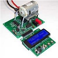
... Application Board ® The Atmel ATA6823 application board allows the running motor. The supply voltage 18V, maximum power of the DC motor is limited by the external H-bridge MOSFETs. No microcontroller is implemented on-board possible to con- trol the motor either via an external microcontroller (with or without LIN bus), or directly (using the DIR and PWM pins) ...
Page 2
... Figure 2-1. Atmel ATA6823 2 Application Board 4961B–AUTO–02/11 ...
Page 3
... Figure 2-2. Atmel ATA6823 Application Board Schematic 4961B–AUTO–02/ PBAT DG1 DG2 DG3 28 13 PGND VCO EN1 30 11 VBAT PWM 31 10 VBATSW DIR 32 9 EN2 TX Atmel ATA6823 3 ...
Page 4
... Figure 2-3. Atmel ATA6823 Application Board Component Placement; Top Side, Top View Atmel ATA6823 4 4961B–AUTO–02/11 ...
Page 5
... Figure 2-4. Atmel ATA6823 Application Board; Top Side, Top View Figure 2-5. Atmel ATA6823 Application Board; Bottom Side, Top View (as if PCB Were Transparent) 4961B–AUTO–02/11 Atmel ATA6823 5 ...
Page 6
... XS2 Atmel ATA6823 pin 19, S2 output to control external H-bridge 4 XS1 Atmel ATA6823 pin 17, S1 output to control external H-bridge 5 XH2 Atmel ATA6823 pin 20, H2 output to control external H-bridge 6 XH1 Atmel ATA6823 pin 18, H1 output to control external H-bridge Atmel ATA6823 6 Description VCC regulator output, voltage level depends on jumper JP2 setting ...
Page 7
... EN2 2.2 Getting Started To run the ATA6823 application board 18V supply voltage between VBAT and GND is necessary. To check the board at start up, following voltages are measurable at 12.5V VBAT voltage. After the power supply is switched on, a level measurable at VINT and the header pin VCC ...
Page 8
... According to LIN specification 2.0, resistor R4 is not necessary when using the Atmel ATA6823 as slave. This is the default at delivery. To change the Atmel ATA6823 LIN from slave mode to master mode, complying with LIN specification 2.0, a 1kΩ resistor has to be inserted in place of R4, and reverse battery protec- tion diode has to be inserted in place of D3 ...
Page 9
... Optionally, the watchdog frequency can be changed via resistor R5, by setting jumper RWD to position 1-2. Either SMD (R5A) or wired (R5B) resistors may be used. 4961B–AUTO–02/ the shunt can be connected to the AD converter of the microcontroller. Watchdog Resistor Placement Atmel ATA6823 Table 2-2 on page 6). All pins Table 2-4 on page 7). ...
Page 10
... Enable After power-on, the Atmel ATA6823 is in run mode. A falling edge at pin EN1 switches the device to standby mode. Switching Atmel ATA6823 back to run mode is possible either by switching LIN to GND or by switching EN2 to VBAT ...
Page 11
... If overtemperature of higher than 150°C is detected, the pin DG3 is set to high. The occur- rence of overtemperature will be latched until the next watchdog pulse. If monitoring signals DG2 or DG3 indicate failure, the ATA6823 will switch off the motor bridge. 3.5 Motor Bridge OFF When the PWM signal is set to low, both high-side MOSFETs are switched on to slow the motor down ...
Page 12
... Add-on Microcontroller Module to Generate WD and PWM The WD and PWM signals are necessary to activate the Atmel ATA6823 H-bridge as shown in Table 2-2 on page ATA6823-DK2 V1.0), assembled with Atmel ATmega88, is included. The module works with both Atmel ATA6823 digital supply voltages well as 3.3V. Table 4-1. ...
Page 13
... Push button Ramp3 is defined to switch Atmel troller will no longer be supplied with VCC voltage. System wake-up can only be triggered by Atmel ATA6823. Either ground level on the LIN bus or push button EN2 wakes up the Atmel ATA6823. The controller is supplied again and begins to work. 4.5 ...
Page 14
... Figure 4-1. Add-on Atmel Atmega88 Module ATA6823-DK2 V1.0 for Generating WD and PWM For further information please refer to the datasheet for the Atmel ATA6823. Atmel ATA6823 14 4961B–AUTO–02/11 ...
Page 15
... Disclaimer: The information in this document is provided in connection with Atmel products. No license, express or implied, by estoppel or otherwise, to any intellec- tual property right is granted by this document or in connection with the sale of Atmel products. EXCEPT AS SET FORTH IN THE ATMEL TERMS AND CONDITIONS OF SALES LOCATED ON THE ATMEL WEBSITE, ATMEL ASSUMES NO LIABILITY WHATSOEVER AND DISCLAIMS ANY EXPRESS, IMPLIED OR STATUTORY WARRANTY RELATING TO ITS PRODUCTS INCLUDING, BUT NOT LIMITED TO, THE IMPLIED WARRANTY OF MERCHANTABILITY, FITNESS FOR A PARTICU- LAR PURPOSE, OR NON-INFRINGEMENT ...