ATA6823-DK Atmel, ATA6823-DK Datasheet - Page 10
ATA6823-DK
Manufacturer Part Number
ATA6823-DK
Description
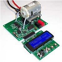
BOARD EVALUATION FOR ATA6823
Manufacturer
Atmel
Type
PWM Controllersr
Specifications of ATA6823-DK
Main Purpose
Power Management, Motor Control
Embedded
No
Utilized Ic / Part
ATA6823
Primary Attributes
Brush DC Motors, 8 ~ 18V, LIN Interface, Watchdog, 5V Regulator
Secondary Attributes
Cross Conduction, Under/Over Voltage, Short Circuit, & Temperature Protection
Input Voltage
8 V to 18 V
Product
Power Management Modules
Lead Free Status / RoHS Status
Contains lead / RoHS non-compliant
For Use With/related Products
ATA6823


3. Application Hints
3.1
3.2
3.3
3.4
10
Trigger Watchdog
Wake-up Source Recognition
Diagnostic Pins
Enable
Atmel ATA6823
To switch Atmel
nal to the pin WD. If R6 = R
adapt the resistor to other values, refer to the datasheet for Atmel
section title Reset and Watchdog Management.
The trigger signal has no integrated debouncing circuit. It switches with a rising edge at pin
WD.
Operating mode is shown by permanently high level at pin /RESET.
A wrong or missing trigger pulse generates a reset pulse with length of 2ms. VCC voltage
lower than the reset threshold generates a reset pulse for 68ms.
After power-on, the Atmel ATA6823 is in run mode. A falling edge at pin EN1 switches the
device to standby mode.
Switching Atmel ATA6823 back to run mode is possible either by switching LIN to GND or by
switching EN2 to VBAT.
EN2 can be switched up to VBAT. EN1 uses 5V logic and would be destroyed by switching to
the VBAT level.
Diagnostic pin DG1 has a double assignment: Until the first watch dog pulse, DG1 shows the
wake up source; a high level at pin DG1 indicates that EN2 is the wake-up source, while a low
level indicates LIN was wake-up source.
Table 3-1.
There are three diagnostic pins available to detect errors (see
The Atmel ATA6823 has neither short-circuit shutdown nor short-circuit limitation. Short circuit
is indicated, handling must be done by the microcontroller.
While the outputs are switched on, the voltage levels between the active MOSFET sources
and drains are monitored. If one voltage level is higher than 4V, DG1 will be set to high. After
switching the motor bridge, either by PWM or by DIR, the sense monitoring is deactivated for
10µs. Otherwise inrush or switching currents will activate the DG1 warning.
Supply voltage breakdown at pin PBAT under the level of 5.6V is indicated by a high level at
pin DG1, without any delay time.
Signal
DG1
DG2
DG3
Diagnostic Pins
®
ATA6823 into operating mode, it is necessary to apply a correct trigger sig-
Description
Short circuit
Supply monitoring, charge pump
Overtemperature warning
WD
= 33kΩ, a square wave trigger signal of f = 70Hz is required. To
Table 3-1 on page
®
ATA6823, especially the
4961B–AUTO–02/11
10).
Related parts for ATA6823-DK
Image
Part Number
Description
Manufacturer
Datasheet
Request
R

Part Number:
Description:
IC H-BRIDGE MOTOR DRIVER 32-QFN
Manufacturer:
Atmel
Datasheet:

Part Number:
Description:
Motor / Motion / Ignition Controllers & Drivers Gate Driver IC
Manufacturer:
Atmel
Datasheet:

Part Number:
Description:
H-bridge Motor Driver
Manufacturer:
ATMEL Corporation
Datasheet:

Part Number:
Description:
DEV KIT FOR AVR/AVR32
Manufacturer:
Atmel
Datasheet:
Part Number:
Description:
INTERVAL AND WIPE/WASH WIPER CONTROL IC WITH DELAY
Manufacturer:
ATMEL Corporation
Datasheet:
Part Number:
Description:
Low-Voltage Voice-Switched IC for Hands-Free Operation
Manufacturer:
ATMEL Corporation
Datasheet:
Part Number:
Description:
MONOLITHIC INTEGRATED FEATUREPHONE CIRCUIT
Manufacturer:
ATMEL Corporation
Datasheet:
Part Number:
Description:
AM-FM Receiver IC U4255BM-M
Manufacturer:
ATMEL Corporation
Datasheet:
Part Number:
Description:
Monolithic Integrated Feature Phone Circuit
Manufacturer:
ATMEL Corporation
Datasheet:
Part Number:
Description:
Multistandard Video-IF and Quasi Parallel Sound Processing
Manufacturer:
ATMEL Corporation
Datasheet:
Part Number:
Description:
High-performance EE PLD
Manufacturer:
ATMEL Corporation
Datasheet:
Part Number:
Description:
8-bit Flash Microcontroller
Manufacturer:
ATMEL Corporation
Datasheet: