ATA6823-DK Atmel, ATA6823-DK Datasheet - Page 13
ATA6823-DK
Manufacturer Part Number
ATA6823-DK
Description
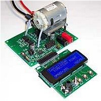
BOARD EVALUATION FOR ATA6823
Manufacturer
Atmel
Type
PWM Controllersr
Specifications of ATA6823-DK
Main Purpose
Power Management, Motor Control
Embedded
No
Utilized Ic / Part
ATA6823
Primary Attributes
Brush DC Motors, 8 ~ 18V, LIN Interface, Watchdog, 5V Regulator
Secondary Attributes
Cross Conduction, Under/Over Voltage, Short Circuit, & Temperature Protection
Input Voltage
8 V to 18 V
Product
Power Management Modules
Lead Free Status / RoHS Status
Contains lead / RoHS non-compliant
For Use With/related Products
ATA6823


4.2
4.3
4.4
4.5
4961B–AUTO–02/11
Operating Functions
Sleep Mode
Diagnosis
PWM
The module also provides the PWM signal with duty cycle from 0% to 100%, adjustable by
speed potentiometer (see
f
The microcontroller module is turnable via operating elements as described in
page
Two different operating modes are available:
Push button Ramp3 is defined to switch Atmel
troller will no longer be supplied with VCC voltage.
System wake-up can only be triggered by Atmel ATA6823.
Either ground level on the LIN bus or push button EN2 wakes up the Atmel ATA6823. The
controller is supplied again and begins to work.
If a short circuit is indicated by diagnosis pin DG1, the microcontroller will switch off the
H-bridge immediately. Turning it on again is locked. Push button Ramp1 controls the unlock
function.
DG2 voltage diagnosis also causes the switching off of the gate driver. To release, use push
button Ramp2.
Overtemperature DG3 warning is indicated in the display, the H-bridge stops.
The overtemperature signaling is not latched, after cooling down the signal disappears, the
H-bridge starts running again.
PWM
1. Manual mode:
2. Automatic ramp mode:
Rotation direction is selected using the direction switch, and the generated PWM fre-
quency responds to the PWM potentiometer.
Pressing push button Ramp1 causes a triangle-duty-cycle PWM curve to be generated.
The low value is zero, the maximum value is the set value of the speed potentiometer. The
ramp will be stopped by pressing push button Ramp2.
= 25kHz.
12.
Table
4-1). The PWM frequency of the example program is
®
ATA6823 into standby mode. The microcon-
Atmel ATA6823
Table 4-1 on
13
Related parts for ATA6823-DK
Image
Part Number
Description
Manufacturer
Datasheet
Request
R

Part Number:
Description:
IC H-BRIDGE MOTOR DRIVER 32-QFN
Manufacturer:
Atmel
Datasheet:

Part Number:
Description:
Motor / Motion / Ignition Controllers & Drivers Gate Driver IC
Manufacturer:
Atmel
Datasheet:

Part Number:
Description:
H-bridge Motor Driver
Manufacturer:
ATMEL Corporation
Datasheet:

Part Number:
Description:
DEV KIT FOR AVR/AVR32
Manufacturer:
Atmel
Datasheet:
Part Number:
Description:
INTERVAL AND WIPE/WASH WIPER CONTROL IC WITH DELAY
Manufacturer:
ATMEL Corporation
Datasheet:
Part Number:
Description:
Low-Voltage Voice-Switched IC for Hands-Free Operation
Manufacturer:
ATMEL Corporation
Datasheet:
Part Number:
Description:
MONOLITHIC INTEGRATED FEATUREPHONE CIRCUIT
Manufacturer:
ATMEL Corporation
Datasheet:
Part Number:
Description:
AM-FM Receiver IC U4255BM-M
Manufacturer:
ATMEL Corporation
Datasheet:
Part Number:
Description:
Monolithic Integrated Feature Phone Circuit
Manufacturer:
ATMEL Corporation
Datasheet:
Part Number:
Description:
Multistandard Video-IF and Quasi Parallel Sound Processing
Manufacturer:
ATMEL Corporation
Datasheet:
Part Number:
Description:
High-performance EE PLD
Manufacturer:
ATMEL Corporation
Datasheet:
Part Number:
Description:
8-bit Flash Microcontroller
Manufacturer:
ATMEL Corporation
Datasheet: