ATA6823-DK Atmel, ATA6823-DK Datasheet - Page 12
ATA6823-DK
Manufacturer Part Number
ATA6823-DK
Description
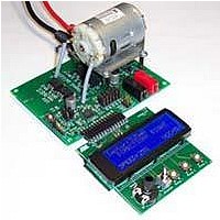
BOARD EVALUATION FOR ATA6823
Manufacturer
Atmel
Type
PWM Controllersr
Specifications of ATA6823-DK
Main Purpose
Power Management, Motor Control
Embedded
No
Utilized Ic / Part
ATA6823
Primary Attributes
Brush DC Motors, 8 ~ 18V, LIN Interface, Watchdog, 5V Regulator
Secondary Attributes
Cross Conduction, Under/Over Voltage, Short Circuit, & Temperature Protection
Input Voltage
8 V to 18 V
Product
Power Management Modules
Lead Free Status / RoHS Status
Contains lead / RoHS non-compliant
For Use With/related Products
ATA6823


4. Add-on Microcontroller Module to Generate WD and PWM
4.1
12
Watchdog
Atmel ATA6823
The WD and PWM signals are necessary to activate the Atmel ATA6823 H-bridge as shown in
Table 2-2 on page
ATA6823-DK2 V1.0), assembled with Atmel ATmega88, is included. The module works with
both Atmel ATA6823 digital supply voltages, 5V as well as 3.3V.
Table 4-1.
The module generates a trigger signal of approximately f
of the default watchdog resistor R
Potentiometer
3. Short between dynamic clamp (PWM) and ground
4. Short between dynamic clamp and supply pin PBAT after inverse polarity protection
5. Short between dynamic clamp and supply before inverse polarity protection
Push button
Push button
Push button
For an ideal short circuit, supply voltage higher than 8V and ON duty cycle higher than
10µs, the sense pin S1 or S2 will switch the pin DG1.
For non-ideal short circuit or lower supply voltages, PBAT monitoring will switch DG1.
There is an 18V zener diode between Hx and Sx. In case of higher supply voltages and
short between dynamic clamp and GND, the charge pump capacity will be discharged
over this 18V clamping structure. If voltage at VRES minus voltage at PBAT is lower than
5V, after 30 µs, DG2 will be set and the output switches will be switched off.
For an ideal short circuit, supply voltage higher than 8V and ON duty cycle higher than
10µs causes a voltage drop higher than 4V at least across output FET. The sense pins S1
or S2 will switch the pin DG1.
During other conditions, PBAT monitoring will switch DG1.
For ON duty cycle higher than 10µs, sense pin S1 or S2 will switch pin DG1.
A short circuit cannot be detected with the diagnostic pins of the Atmel
duty cycle shorter than 10µs. Usually the motor will not move, and the servo loop will sig-
nal deadlock.
Switch
Type
Add-on Module Operating Elements
Name
Direction
6. Therefore, the microcontroller module
Ramp1
Ramp2
Ramp3
Speed
Function
Start ramp release DG1 signals: short circuit
Stop ramp release DG2 signals: charge pump,
overvoltage/undervoltage detection
Switch system into sleep mode
Left – Off – Right
PWM frequency
WD
= R6 = 33kΩ.
WD
= 70Hz, which is required in case
(Figure 4-1 on page
®
ATA6823 for a
4961B–AUTO–02/11
14, Atmel
Related parts for ATA6823-DK
Image
Part Number
Description
Manufacturer
Datasheet
Request
R

Part Number:
Description:
IC H-BRIDGE MOTOR DRIVER 32-QFN
Manufacturer:
Atmel
Datasheet:

Part Number:
Description:
Motor / Motion / Ignition Controllers & Drivers Gate Driver IC
Manufacturer:
Atmel
Datasheet:

Part Number:
Description:
H-bridge Motor Driver
Manufacturer:
ATMEL Corporation
Datasheet:

Part Number:
Description:
DEV KIT FOR AVR/AVR32
Manufacturer:
Atmel
Datasheet:
Part Number:
Description:
INTERVAL AND WIPE/WASH WIPER CONTROL IC WITH DELAY
Manufacturer:
ATMEL Corporation
Datasheet:
Part Number:
Description:
Low-Voltage Voice-Switched IC for Hands-Free Operation
Manufacturer:
ATMEL Corporation
Datasheet:
Part Number:
Description:
MONOLITHIC INTEGRATED FEATUREPHONE CIRCUIT
Manufacturer:
ATMEL Corporation
Datasheet:
Part Number:
Description:
AM-FM Receiver IC U4255BM-M
Manufacturer:
ATMEL Corporation
Datasheet:
Part Number:
Description:
Monolithic Integrated Feature Phone Circuit
Manufacturer:
ATMEL Corporation
Datasheet:
Part Number:
Description:
Multistandard Video-IF and Quasi Parallel Sound Processing
Manufacturer:
ATMEL Corporation
Datasheet:
Part Number:
Description:
High-performance EE PLD
Manufacturer:
ATMEL Corporation
Datasheet:
Part Number:
Description:
8-bit Flash Microcontroller
Manufacturer:
ATMEL Corporation
Datasheet: