ATA6826-DK Atmel, ATA6826-DK Datasheet
ATA6826-DK
Specifications of ATA6826-DK


Related parts for ATA6826-DK


ATA6826-DK Summary of contents
Page 1
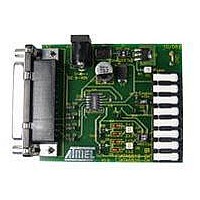
... Design Kit The design kit includes the following components: • ATA6826 design software • Basic application board ATA6826-DK • Link cable to PC, 25-lead 1:1 • Application note • Datasheet “ATA6826: Triple Half-bridge DMOS Output Driver with Serial Input Control” ...
Page 2
... Features • Screwless row connector pins for external loads switched by low-side or high-side drivers • Easy adaptation of loads directly on the ATA6826 design kit • Direct switch of loads to V • Forward/reverse rotation of DC motors by full-bridge application • Paralleling of outputs for powerful applications • ...
Page 3
... Figure 2-2. ATA6826-DK Basic Application Board Schematic LM2936 D1 BYV28 S1 C2 100 100 µF 4981A–AUTO–02/ 200 HS3 S2 C4 100 µ OUT1 D8b D6 MB23 MB32 D5 D8a D7b D4 OUT2 MB12 MB21 D3 D7a OUT3 ATA6826 3 ...
Page 4
... Figure 2-3. Figure 2-4. ATA6826 4 ATA6826-DK Design Kit, Basic Application Board Component Placement; Top Side, Top View ATA6826-DK Design Kit, Basic Application Board Top Side, Top View 4981A–AUTO–02/07 ...
Page 5
... Use the enclosed parallel cable to connect the PC’s parallel port to the basic application board. Double-clicking on the ATA6826 icon 3-1) starts the software user interface. Figure 3-1. 4981A–AUTO–02/07 ATA6826-DK Design Kit, Basic Application Board; Bottom Side, Top View (as if PCB were Transparent) Software Icon ATA6826 (Figure ...
Page 6
... Description The ATA6826 design kit and the software user interface show the principal functions of the ATA6826, and enables the designer to directly create a design according to current needs. The software user interface includes all functions of the ATA6826 and provides convenient control of the ATA6826 via the basic application board. Use the adjust register (representing the microcon- ...
Page 7
... LS3 See LS1 6 HS3 See HS1 7 n.u. Not used 8 n.u. Not used 9 n.u. Not used 10 n.u. Not used 11 n.u. Not used 12 n.u. Not used 13 OCS Overcurrent shutdown (high = overcurrent shutdown is active) 14 n.u. Not used 15 n.u. Not used 4981A–AUTO–02/07 ATA6826 7 ...
Page 8
... When operating in a safety-critical environment, the use of a separate watchdog IC is recom- mended (for example, U5021M). Unlike other circuits of the Atmel driver family, the open-load detection of ATA6826 is active for all output stages that are currently switched on. If the current through any high-side or low-side switch does not reach the open-load-detection threshold, an open-load is detected: in the output register the OPL bit is set to high ...
Page 9
... Configuration Table of the Required Datawords to Set Certain Functions of the Application Circuit (See Figure 4-1 on page Bit 13 Bit 6 Bit 5 (OCS) (HS3) (LS3 not care for this demonstration; if set to high: overcurrent shutdown is active ATA6826 10) Bit 4 Bit 3 Bit 2 Bit 1 (HS2) (LS2) (HS1) (LS1 Bit 0 ...
Page 10
... Figure 4-1. Application With Microcontroller and Watchdog V S Enable Trigger U5021M V Reset CC WATCHDOG ATA6826 10 V BATT 13V BYW32 V CC Microcontroller OUT1 13 M1 OUT2 12 M2 OUT3 4981A–AUTO–02/07 ...
Page 11
... Parallel Operation of Several ATA6826s In applications with a high number of loads, parallel operation of the ATA6826 via the microcon- troller is possible. Separate control of the ATA6826’s serial peripheral interface is provided by chip select pins CS1 to CS4 (for the function of the serial peripheral interface, please refer to the datasheet). ...
Page 12
... In applications with a larger number of loads, there's a second option for connecting several ATA6826s to the microcontroller. The daisy-chain arrangement requires only one CS line; the data signal is handed over step-by-step from one ATA6826 to the next as long as the CS signal stays low. It should be evident that this advantage is traded for slower reaction times, as several programming cycles are needed to load the desired setting into each ATA6826 ...
Page 13
... The IC should be connected to a cooling area onboard. All thermal pins (4 GND pins) are directly connected to the cooling area. housing of the ATA6826. The cooling area extension should be increased or decreased accord- ing to the required power dissipation (see as follows: 2 × L² = cooling area extension [mm²]. ...
Page 14
... Overload Considerations 6.1 Driver Output Shorted to V During normal operation, ATA6826 is protected against short circuits by an overcurrent limita- tion. However, some attention has to be paid to certain abnormal operating conditions that might occur in practice. In particular, we have to consider the case of an output shorted to V the IC is not connected to supply voltage V current flows from the shorted output via the voltage supply pin to the capacitor C1 ...
Page 15
... Figure 6-3. The clamping structures at the output stages limit the voltage peak and provide a path for the current after switching off. The maximum inductive shutdown energy for ATA6826 is specified as 15 mJ. This value applies for both low-side and high-side outputs. The energy W ...
Page 16
... IC can also be neglected. This means that during long periods in inhibit mode, the IC's supply voltage could increase con- tinuously until the maximum supply voltage limit of 40V is exceeded, damaging the IC. ATA6826 therefore features a discharger circuit that prevents such unwanted effects ...
Page 17
... Disclaimer: The information in this document is provided in connection with Atmel products. No license, express or implied, by estoppel or otherwise, to any intellectual property right is granted by this document or in connection with the sale of Atmel products. EXCEPT AS SET FORTH IN ATMEL’S TERMS AND CONDI- TIONS OF SALE LOCATED ON ATMEL’S WEB SITE, ATMEL ASSUMES NO LIABILITY WHATSOEVER AND DISCLAIMS ANY EXPRESS, IMPLIED OR STATUTORY WARRANTY RELATING TO ITS PRODUCTS INCLUDING, BUT NOT LIMITED TO, THE IMPLIED WARRANTY OF MERCHANTABILITY, FITNESS FOR A PARTICULAR PURPOSE, OR NON-INFRINGEMENT ...