ATA6826-DK Atmel, ATA6826-DK Datasheet - Page 16
ATA6826-DK
Manufacturer Part Number
ATA6826-DK
Description
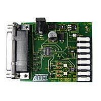
BOARD EVALUATION FOR ATA6826
Manufacturer
Atmel
Specifications of ATA6826-DK
Main Purpose
Power Management, Half H-Bridge Driver (Internal FET)
Embedded
No
Utilized Ic / Part
ATA6826
Primary Attributes
3 Half H-Bridge Drivers, 1A, 2 kV ESD Protection
Secondary Attributes
Short-Circuit, Thermal & Undervoltage Protection
Lead Free Status / RoHS Status
Contains lead / RoHS non-compliant


6.3
16
Discharger Circuit
ATA6826
Figure 6-4.
Many typical applications use an inverse-polarity protection diode, such as D1 in
the power-supply feed to prevent any damage if V
the popularity of this method, it involves a certain danger.
During inhibit mode, the IC consumes only an extremely low current I
mum. Any peaks on the supply voltage (V
capacitor (C9 in
due to the extremely small quiescent current, discharging via the IC can also be neglected.
This means that during long periods in inhibit mode, the IC's supply voltage could increase con-
tinuously until the maximum supply voltage limit of 40V is exceeded, damaging the IC. ATA6826
therefore features a discharger circuit that prevents such unwanted effects. If V
threshold value of approximately 27V, the blocking capacitor is discharged via an integrated
resistor until V
Figure 6-5.
S
Inductive Pulse at Low-side Output;
Channel 1: Gradient of V
(200 mA/Div.), Pulse Energy: W
Functional Principle of the Discharger Circuit
again falls below the threshold.
Figure
ATA6826
6-5). D1 prevents the capacitor from discharging via the power supply;
26.8V
2 k
out
(10V offset), Channel 4: Gradient of I
pk
V
S
in
L
= 5 mJ
Figure
C1
S
is applied with the wrong polarity. Despite
D1
6-5) will gradually charge the blocking
V
batt
VS
V
, such as 20 µA at maxi-
pk
out
4981A–AUTO–02/07
Figure
S
exceeds a
6-5, in
Related parts for ATA6826-DK
Image
Part Number
Description
Manufacturer
Datasheet
Request
R

Part Number:
Description:
Triple Half-bridge DMOS Output Driver with Serial Input Control
Manufacturer:
ATMEL Corporation
Datasheet:

Part Number:
Description:
MOSFET & Power Driver ICs Triple Half-Bridge Driver
Manufacturer:
Atmel
Datasheet:
Part Number:
Description:
MOSFET & Power Driver ICs Triple Half-Bridge Driver
Manufacturer:
Atmel
Datasheet:

Part Number:
Description:
DEV KIT FOR AVR/AVR32
Manufacturer:
Atmel
Datasheet:
Part Number:
Description:
INTERVAL AND WIPE/WASH WIPER CONTROL IC WITH DELAY
Manufacturer:
ATMEL Corporation
Datasheet:
Part Number:
Description:
Low-Voltage Voice-Switched IC for Hands-Free Operation
Manufacturer:
ATMEL Corporation
Datasheet:
Part Number:
Description:
MONOLITHIC INTEGRATED FEATUREPHONE CIRCUIT
Manufacturer:
ATMEL Corporation
Datasheet:
Part Number:
Description:
AM-FM Receiver IC U4255BM-M
Manufacturer:
ATMEL Corporation
Datasheet:
Part Number:
Description:
Monolithic Integrated Feature Phone Circuit
Manufacturer:
ATMEL Corporation
Datasheet:
Part Number:
Description:
Multistandard Video-IF and Quasi Parallel Sound Processing
Manufacturer:
ATMEL Corporation
Datasheet:
Part Number:
Description:
High-performance EE PLD
Manufacturer:
ATMEL Corporation
Datasheet:
Part Number:
Description:
8-bit Flash Microcontroller
Manufacturer:
ATMEL Corporation
Datasheet: