AD5259EVAL Analog Devices Inc, AD5259EVAL Datasheet - Page 20
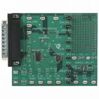
AD5259EVAL
Manufacturer Part Number
AD5259EVAL
Description
BOARD EVAL FOR AD5259 DGTL POT
Manufacturer
Analog Devices Inc
Datasheet
1.AD5259BRMZ10.pdf
(24 pages)
Specifications of AD5259EVAL
Main Purpose
Digital Potentiometer
Utilized Ic / Part
AD5259
Lead Free Status / RoHS Status
Contains lead / RoHS non-compliant
Secondary Attributes
-
Embedded
-
Primary Attributes
-
Lead Free Status / Rohs Status
Not Compliant


AD5259
DISPLAY APPLICATIONS
CIRCUITRY
A special feature of the AD5259 is its unique separation of the
V
flexibility in applications that do not always provide needed
supply voltages.
In particular, LCD panels often require a V
range of 3 V to 5 V. The circuit in Figure 46 is the rare excep-
tion in which a 5 V supply is available to power the digital
potentiometer.
1F
In the more common case shown in Figure 47, only analog 14.4 V
and digital logic 3.3 V supplies are available. By placing discrete
resistors above and below the digital potentiometer, V
now be tapped off the resistor string itself. Based on the chosen
resistor values, the voltage at V
allowing the wiper to be safely operated all the way up to 4.8 V.
The current draw of V
it is only on the order of microamps. V
3.3 V digital supply because V
is needed when writing to the EEPROM. It would be imprac-
tical to try and source 35 mA through the 70 kΩ resistor,
therefore, V
C1
LOGIC
VCC (~3.3V)
MCU
and V
10k
R6
LOGIC
DD
10k
R5
supply pins. The separation provides greater
Figure 46. V
is not connected to the same node as V
5V
AD5259
DD
V
V
SCL
SDA
GND
DD
LOGIC
will not affect that node’s bias because
COM
14.4V
A
B
Adjustment Application
LOGIC
R1
70k
R2
10k
R3
25k
DD
W
in this case equals 4.8 V,
will draw the 35 mA which
LOGIC
–
+
AD8565
U1
COM
is tied to the MCU’s
voltage in the
3.5V < V
DD
COM
DD
can
.
< 4.5V
Rev. B | Page 20 of 24
For this reason, V
supply pins that can either be tied together or treated inde-
pendently; V
and V
flexibility.
1F
For a more detailed look at this application, refer to the article,
“Simple VCOM Adjustment uses any Logic Supply Voltage” in
the September 30, 2004 issue of EDN magazine.
C1
VCC (~3.3V)
Figure 47. Circuitry When a Separate Supply is Not Available for V
MCU
DD
10k
biasing up the A, B, and W terminals for added
R6
SUPPLIES POWER
TO BOTH THE
MICRO AND THE
LOGIC SUPPLY OF
THE DIGITAL POT
LOGIC
10k
R5
LOGIC
supplying the logic/EEPROM with power,
AD5259
and V
V
V
SCL
SDA
GND
DD
LOGIC
14.4V
DD
A
B
R1
70k
R2
10k
R3
25k
are provided as two separate
W
–
+
AD8565
U1
3.5V < V
COM
DD
< 4.5V
Related parts for AD5259EVAL
Image
Part Number
Description
Manufacturer
Datasheet
Request
R


Part Number:
Description:
±1.7g Dual-Axis IMEMS Accelerometer Evaluation Board
Manufacturer:
Analog Devices Inc
Datasheet:

Part Number:
Description:
Inertial Sensor Evaluation System
Manufacturer:
Analog Devices Inc
Datasheet:
Part Number:
Description:
Manufacturer:
Analog Devices Inc
Datasheet:
Part Number:
Description:
Manufacturer:
Analog Devices Inc
Datasheet:
Part Number:
Description:
Manufacturer:
Analog Devices Inc
Datasheet:
Part Number:
Description:
Manufacturer:
Analog Devices Inc
Datasheet:
Part Number:
Description:
Manufacturer:
Analog Devices Inc
Datasheet:
Part Number:
Description:
Manufacturer:
Analog Devices Inc
Datasheet:
Part Number:
Description:
Manufacturer:
Analog Devices Inc
Datasheet:
Part Number:
Description:
Manufacturer:
Analog Devices Inc
Datasheet:
Part Number:
Description:
Manufacturer:
Analog Devices Inc
Datasheet:
Part Number:
Description:
Manufacturer:
Analog Devices Inc
Datasheet: