EVAL-ADUM4160EBZ Analog Devices Inc, EVAL-ADUM4160EBZ Datasheet - Page 6
EVAL-ADUM4160EBZ
Manufacturer Part Number
EVAL-ADUM4160EBZ
Description
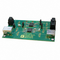
EVALUATION MODULE FOR ADUM4160
Manufacturer
Analog Devices Inc
Series
iCoupler®r
Datasheets
1.ADUM4160BRWZ-RL.pdf
(16 pages)
2.EVAL-ADUM4160EBZ.pdf
(8 pages)
3.EVAL-ADUM4160EBZ.pdf
(14 pages)
Specifications of EVAL-ADUM4160EBZ
Main Purpose
Interface, Digital Isolator
Embedded
No
Utilized Ic / Part
ADuM4160
Primary Attributes
USB Bidirectional Isolation
Secondary Attributes
3.1 V ~ 5.5 V Supply
Silicon Manufacturer
Analog Devices
Application Sub Type
USB Port Isolator
Kit Application Type
Interface
Silicon Core Number
ADuM4160
Lead Free Status / RoHS Status
Lead free / RoHS Compliant
Lead Free Status / RoHS Status
Lead free / RoHS Compliant, Lead free / RoHS Compliant
Other names
Q4508819


ADuM4160
DIN V VDE V 0884-10 (VDE V 0884-10) INSULATION CHARACTERISTICS
These isolators are suitable for reinforced electrical isolation only within the safety limit data. Maintenance of the safety data is ensured by
protective circuits. The * marking on packages denotes DIN V VDE V 0884-10 approval.
Table 5.
Description
Installation Classification per DIN VDE 0110
Climatic Classification
Pollution Degree per DIN VDE 0110, Table 1
Maximum Working Insulation Voltage
Input-to-Output Test Voltage, Method B1
Input-to-Output Test Voltage, Method A
Highest Allowable Overvoltage
Safety-Limiting Values
Insulation Resistance at T
Figure 2. Thermal Derating Curve, Dependence of Safety-Limiting Values
For Rated Mains Voltage ≤ 150 V rms
For Rated Mains Voltage ≤ 300 V rms
For Rated Mains Voltage ≤ 400 V rms
After Environmental Tests Subgroup 1
After Input and/or Safety Test Subgroup 2
and Subgroup 3
Case Temperature
Side 1 Current
Side 2 Current
350
300
250
200
150
100
50
0
0
with Case Temperature per DIN V VDE V 0884-10
50
CASE TEMPERATURE (°C)
SIDE #1
S
SIDE #2
100
150
Conditions
V
partial discharge < 5 pC
V
V
Transient overvoltage, t
Maximum value allowed in the event of a failure
( see Figure 2)
V
IORM
IORM
IORM
IO
= 500 V
× 1.875 = V
× 1.6 = V
× 1.2 = V
200
Rev. Pr F | Page 6 of 14
PR
PR
, t
, t
PR
m
m
, 100% production test, t
= 60 sec, partial discharge < 5 pC
= 60 sec, partial discharge < 5 pC
TR
= 10 seconds
RECOMMENDED OPERATING CONDITIONS
Table 6.
Parameter
Operating Temperature
Supply Voltages
Input Signal Rise and Fall Times
1
All voltages are relative to their respective ground. See the DC Correctness
and Magnetic Field Immunity section for information on immunity to
external magnetic fields.
m
1
= 1 sec,
Preliminary Technical Data
Symbol
V
V
V
V
T
I
I
R
S1
S2
S
IORM
PR
PR
TR
S
Symbol
T
V
A
BUS1
,V
Characteristic
I to IV
I to III
I to II
40/105/21
2
846
1590
1375
1018
6000
150
265
335
>10
BUS2,
9
Min
−40
3.0
Max
+105
5.5
1.0
Unit
V peak
V peak
V peak
V peak
V peak
°C
mA
mA
Ω
Unit
°C
V
ms
Related parts for EVAL-ADUM4160EBZ
Image
Part Number
Description
Manufacturer
Datasheet
Request
R

Part Number:
Description:
EVAL BD For QSOP & SOIC16 Dig Isolators
Manufacturer:
Analog Devices Inc
Datasheet:

Part Number:
Description:
IC, ADJ LDO REG, 1.5V TO 5V 250mA MSOP-8
Manufacturer:
Vishay
Datasheet:

Part Number:
Description:
IC, ADJ LDO REG, 1.5V TO 5V 0.6A 8-TSSOP
Manufacturer:
Vishay
Datasheet:
Part Number:
Description:
IC, ADJ LDO REG, 1.5V TO 5V 250mA MSOP-8
Manufacturer:
Vishay
Datasheet:

Part Number:
Description:
IC ADJ LDO REG 1.5V TO 5V 150mA 5-SOT-23
Manufacturer:
Vishay
Datasheet:

Part Number:
Description:
BOARD EVAL AS1324-AD
Manufacturer:
austriamicrosystems
Datasheet:
Part Number:
Description:
IC, ADJ LDO REG, 1.5V TO 5V 0.6A 8-TSSOP
Manufacturer:
Vishay
Datasheet:

Part Number:
Description:
IC, ADJ LDO REG, 1.5V TO 5V, 0.3A, MSOP8
Manufacturer:
Vishay
Datasheet:
Part Number:
Description:
IC, ADJ LDO REG, 1.5V TO 5V, 0.3A, MSOP8
Manufacturer:
Vishay
Datasheet:
Part Number:
Description:
IC, ADJ LDO REG 1.215V TO 5V 0.3A MSOP-8
Manufacturer:
Vishay
Datasheet:

Part Number:
Description:
±1.7g Dual-Axis IMEMS Accelerometer Evaluation Board
Manufacturer:
Analog Devices Inc
Datasheet:

Part Number:
Description:
IC MULTIPLIER ANALOG 8-SOIC T/R
Manufacturer:
Analog Devices Inc
Datasheet:
Part Number:
Description:
IC ANALOG MULTIPLIER 8-DIP
Manufacturer:
Analog Devices Inc
Datasheet:
Part Number:
Description:
IC ANALOG MULTIPLIER 8-SOIC
Manufacturer:
Analog Devices Inc
Datasheet:
Part Number:
Description:
IC ANALOG MULTIPLIER 8-DIP
Manufacturer:
Analog Devices Inc
Datasheet: