RDK-128 Power Integrations, RDK-128 Datasheet - Page 15
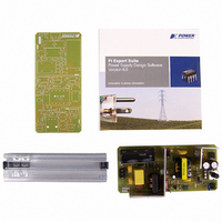
RDK-128
Manufacturer Part Number
RDK-128
Description
KIT REF DESIGN 36-72W MOTOR DRVR
Manufacturer
Power Integrations
Specifications of RDK-128
Main Purpose
Power Management, Motor Control
Embedded
No
Utilized Ic / Part
PKS606
Primary Attributes
Variable Speed 12V 36W DC Motor, 90 ~ 265 VAC
Secondary Attributes
External Potentiometer or Variable DC Voltage Speed Control
Lead Free Status / RoHS Status
Not applicable / Not applicable
Other names
596-1198


16-Aug-07
8 Transformer Spreadsheet
Page 15 of 32
ENTER APPLICATION VARIABLES
VACMIN
VACMAX
fL
Nominal Output Voltage (VO)
Maximum Output Current (IO)
Continuous Power
Peak Power
n
Z
tC Estimate
CIN
ENTER PeakSwitch VARIABLES
PeakSwitch
Chosen Device
ILIMITMIN
ILIMITMAX
fSmin
I^2fmin
VOR
VDS
VD
VDB
VCLO
KP (STEADY STATE)
KP (TRANSIENT)
ENTER UVLO VARIABLES
V_UV_TARGET
V_UV_ACTUAL
RUV_IDEAL
RUV_ACTUAL
BIAS WINDING VARIABLES
VB
NB
PIVB
ENTER TRANSFORMER CORE/CONSTRUCTION VARIABLES
Core Type
Core
Bobbin
ACDC_PeakSwitch_020107;
Rev.1.13; Copyright Power
Minimum Output Voltage at Peak Load
Integrations 2007
PKS606Y
INPUT
180.00
120.00
12.00
35.00
EE25
6.00
0.68
3.00
265
90
50
RDR-128 36 W, 72 W Peak Variable Output Power Supply
PKS6
INFO
EE25
06Y
EE25_BOBBIN
PKS606Y
OUTPUT
250000
12.00
35.00
72.00
2.600
3.000
15.00
EE25
1955
0.60
0.47
0.29
3.75
3.90
180
120
200
100
0.7
0.7
10
96
65
5
Amps
Watts
Watts
mSec
Amps
Amps
Hertz
Hertz
UNIT
Volts
Volts
Volts
Volts
A^2k
Volts
Volts
Volts
Volts
Volts
Volts
Volts
Volts
Volts
onds
uFar
Moh
Moh
ads
ms
ms
Hz
P/N:
P/N:
Tel: +1 408 414 9200 Fax: +1 408 414 9201
ACDC_PeakSwitch_020107_Rev1-13.xls;
PeakSwitch Continuous/Discontinuous Flyback
Transformer Design Spreadsheet
Customer
Minimum AC Input Voltage
Maximum AC Input Voltage
AC Mains Frequency
Nominal Output Voltage (at continuous power)
Power Supply Output Current (corresponding to peak
power)
Minimum Output Voltage at Peak Power (Assuming
output droop during peak load)
Continuous Output Power
Peak Output Power
Efficiency Estimate at output terminals and at peak
load. Enter 0.7 if no better data available
Loss Allocation Factor (Z = Secondary side losses /
Total losses)
Bridge Rectifier Conduction Time Estimate
Input Capacitance
PeakSwitch device
Minimum Current Limit
Maximum Current Limit
Minimum Device Switching Frequency
I^2f (product of current limit squared and frequency is
trimmed for tighter tolerance)
Reflected Output Voltage (VOR <= 135 V
Recommended)
PeakSwitch on-state Drain to Source Voltage
Output Winding Diode Forward Voltage Drop
Bias Winding Diode Forward Voltage Drop
Nominal Clamp Voltage
Ripple to Peak Current Ratio (KP < 6)
Ripple to Peak Current Ratio under worst case at
peak load (0.25 < KP < 6)
Target DC under-voltage threshold, above which the
power supply with start
Typical DC start-up voltage based on standard value
of RUV_ACTUAL
Calculated value for UV Lockout resistor
Closest standard value of resistor to RUV_IDEAL
Bias winding Voltage
Number of Bias Winding Turns
Bias rectifier Maximum Peak Inverse Voltage
User Selected Core Size(Verify acceptable thermal
rise under continuous load conditions)
PC40EE25-Z
EE25_BOBBIN
Power Integrations
www.powerint.com
Related parts for RDK-128
Image
Part Number
Description
Manufacturer
Datasheet
Request
R

Part Number:
Description:
KIT REF DESIGN FOR LNK457D
Manufacturer:
Power Integrations
Datasheet:

Part Number:
Description:
REFERENCE DESIGN LINKSWITCH-PH
Manufacturer:
Power Integrations
Datasheet:

Part Number:
Description:
KIT REF DESIGN FOR LNK403EG
Manufacturer:
Power Integrations
Datasheet:

Part Number:
Description:
KIT REF DESIGN FOR LNK406EG
Manufacturer:
Power Integrations
Datasheet:

Part Number:
Description:
KIT REF DESIGN LINKSWITCH-CV
Manufacturer:
Power Integrations
Datasheet:

Part Number:
Description:
KIT REF DESIGN LINKSWITCH 2
Manufacturer:
Power Integrations
Datasheet:

Part Number:
Description:
Specifications: Family: Eval Boards - DC/DC & AC/DC (Off-Line) SMPS ; Series: HiperLCS™ ; Main Purpose: DC/DC, Step Down ; Outputs and Type: 1, Isolated ; Power - Output: 150W ; Voltage - Output: 24V ; Current - Output: 6.25A ; Voltage - Input:
Manufacturer:
Power Integrations, Inc.
Datasheet:

Part Number:
Description:
KIT DESIGN REF TINYSWITCH-III
Manufacturer:
Power Integrations
Datasheet:

Part Number:
Description:
KIT DESIGN REF LINKSWITCH LP
Manufacturer:
Power Integrations
Datasheet:

Part Number:
Description:
KIT REF DESIGN LED LINKSWITCH TN
Manufacturer:
Power Integrations
Datasheet:
Part Number:
Description:
KIT REF DESIGN FOR LNK457D
Manufacturer:
Power Integrations
Datasheet:
Part Number:
Description:
REFERENCE DESIGN LINKSWITCH-PH
Manufacturer:
Power Integrations
Datasheet:
Part Number:
Description:
Specifications: Manufacturer: Power Integrations ; Output Voltage: 380 VDC ; Input / Supply Voltage (Max): 264 VAC ; Input / Supply Voltage (Min): 90 VAC ; Mounting Style: Through Hole ; Output Current: 0.913 A ; Output Power: 347 W
Manufacturer:
Power Integrations, Inc.
Part Number:
Description:
Specifications: Family: Eval Boards - DC/DC & AC/DC (Off-Line) SMPS ; Series: HiperLCS™ ; Main Purpose: DC/DC, Step Down ; Outputs and Type: 1, Isolated ; Power - Output: 150W ; Voltage - Output: 24V ; Current - Output: 6.25A ; Voltage - Input:
Manufacturer:
Power Integrations, Inc.
Datasheet: