CDB3308 Cirrus Logic Inc, CDB3308 Datasheet - Page 34
CDB3308
Manufacturer Part Number
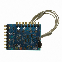
CDB3308
Description
BOARD EVAL FOR CS3308 VOL CTRL
Manufacturer
Cirrus Logic Inc
Specifications of CDB3308
Main Purpose
Audio, Volume Control
Embedded
No
Utilized Ic / Part
CS3308
Primary Attributes
8 Single-Ended Analog Inputs and Outputs, USB or RS232 Interface
Secondary Attributes
Graphic User Interface
Description/function
Audio DSPs
Operating Supply Voltage
5 V
Product
Audio Modules
For Use With/related Products
CS3308
Lead Free Status / RoHS Status
Contains lead / RoHS non-compliant
Lead Free Status / RoHS Status
Lead free / RoHS Compliant, Contains lead / RoHS non-compliant
Other names
598-1496


34
7.4.3
7.5
7.5.1
Reserved
7
Device Configuration 2 - Address 0Ch
Channel B = Channel A (Bit 0 - 3)
Default = 0
Function:
Zero-Crossing Time-Out Period (Bits 4:2)
Default = 011
Function:
When this bit is set, Channel A and Channel B volume levels and muting conditions are controlled by
the Channel A volume and muting register settings, and the Channel B register settings are ignored.
When this bit is cleared, Channel A and Channel B volume and mute settings are independently con-
trolled by the A and B volume and muting bits.
These bits set the zero-crossing time-out period as shown in
Time-Out” section on page 22
Bit Name
Reserved
Ch8=7
Ch6=5
Ch4=3
Ch2=1
6
Bit Setting
Reserved
0
1
0
1
0
1
0
1
5
Channel 7 and 8 mute and volume settings controlled independently
Channel 7 and 8 mute and volume settings controlled by Channel 7 register
settings. Channel 8 register settings are ignored.
Channel 5 and 6 mute and volume settings controlled independently
Channel 5 and 6 mute and volume settings controlled by Channel 5 register
settings. Channel 6 register settings are ignored.
Channel 3 and 4 mute and volume settings controlled independently
Channel 3 and 4 mute and volume settings controlled by Channel 3 register
settings. Channel 4 register settings are ignored
Channel 1 and 2 mute and volume settings controlled independently
Channel 1 and 2 mute and volume settings controlled by Channel 1 register
settings. Channel 2 register settings are ignored
Table 8. Zero-Crossing Time-Out Settings
Table 7. Channel B = Channel A Settings
for more information.
TimeOut2
TimeOut[2:0]
4
000
001
010
011
100
101
110
111
TimeOut1
3
Time-Out Period
Zero-Crossing
Control Configuration
10 ms
15 ms
18 ms
20 ms
30 ms
40 ms
50 ms
5 ms
TimeOut0
Table
2
9. Refer to the
ZCMode1
1
“Zero-Crossing
CS3308
ZCMode0
DS702F1
0
Related parts for CDB3308
Image
Part Number
Description
Manufacturer
Datasheet
Request
R

Part Number:
Description:
Development Kit
Manufacturer:
Cirrus Logic Inc
Datasheet:
Part Number:
Description:
Development Kit
Manufacturer:
Cirrus Logic Inc
Datasheet:


Part Number:
Description:
High-efficiency PFC + Fluorescent Lamp Driver Reference Design
Manufacturer:
Cirrus Logic Inc
Datasheet:
Part Number:
Description:
Development Kit
Manufacturer:
Cirrus Logic Inc
Datasheet:
Part Number:
Description:
Development Kit
Manufacturer:
Cirrus Logic Inc
Datasheet:

Part Number:
Description:
Development Kit
Manufacturer:
Cirrus Logic Inc
Datasheet:
Part Number:
Description:
Development Kit
Manufacturer:
Cirrus Logic Inc
Datasheet:
Part Number:
Description:
Development Kit
Manufacturer:
Cirrus Logic Inc
Datasheet:
Part Number:
Description:
Development Kit
Manufacturer:
Cirrus Logic Inc
Datasheet:

Part Number:
Description:
EVALUATION BOARD FOR CS8427
Manufacturer:
Cirrus Logic Inc
Datasheet:

Part Number:
Description:
BOARD EVAL FOR CS8416 RCVR
Manufacturer:
Cirrus Logic Inc
Datasheet:

Part Number:
Description:
EVALUATION BOARD FOR CS8420
Manufacturer:
Cirrus Logic Inc
Datasheet:

Part Number:
Description:
KIT DEVELOPMENT EP9315 ARM9
Manufacturer:
Cirrus Logic Inc
Datasheet:

Part Number:
Description:
KIT DEVELOPMENT EP9302 ARM9
Manufacturer:
Cirrus Logic Inc
Datasheet: