BP6A-L Powerex Inc, BP6A-L Datasheet - Page 2
BP6A-L
Manufacturer Part Number
BP6A-L
Description
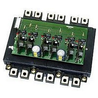
KIT DEV INTERFACE FOR IPM
Manufacturer
Powerex Inc
Datasheet
1.BP6A-L.pdf
(6 pages)
Specifications of BP6A-L
Main Purpose
Power Management, IGBT Power Module Driver
Embedded
No
Utilized Ic / Part
Powerex Intelligent Power Modules (IPM)
Silicon Manufacturer
Powerex
Application Sub Type
IPM Interface
Kit Application Type
Interface
Silicon Core Number
BP6A
Features
Complete Three-phase Isolated Interface Circuit With Fault Feedback
Kit Contents
PCB And Six VLA106-24151 DC To DC Converters
Rohs Compliant
No
Lead Free Status / RoHS Status
Contains lead / RoHS non-compliant
Secondary Attributes
-
Primary Attributes
-
Lead Free Status / RoHS Status
Contains lead / RoHS non-compliant, Contains lead / RoHS non-compliant


Overview:
in gate drive and protection circuits is that the entire family outlined
in Table 1 requires only two different interface circuit designs. The
standard interface circuit consists of opto-couplers to transfer control
signals and isolated power supplies to power the IPM’s internal
circuits. The two circuits are similar except that large L-Series IPMs
in package D utilize separate control grounds on the low side to
minimize ground bounce induced noise. As a result these devices
require six isolated power supplies. The Powerex BP6A reference
design is an example of this circuit.
packages A, B, and C have a common control ground for all three
low side IGBTs. This permits use of a single low side supply so that
only four isolated supplies are required. Interface circuit details for
these devices are available in the Powerex BP7A reference design
application note.
Isolated DC to DC Converters:
power supplies, Powerex has introduced the VLA106-24151 isolated
DC to DC converter shown in figure 2. The VLA106-24151 operates
from a 24V DC supply and produces an isolated 15V DC output at up to
100mA.
between the primary and secondary side. The BP6A board uses six
VLA106-24151 DC to DC converters to supply control power for the L-
Series IPM.
(*) Package Option: B=Solder pin, A=Screw terminal
(#) Circuit Option: R=Six Pack+Brake, C=Six pack
Example:
PM75RLB120 is a 75A, 1200V six pack with brake in a solder pin package
PM450CLA060
PM600CLA060
PM200CLA120
PM300CLA120
PM450CLA120
PM100(#)L(*)060
PM150(#)L(*)060
Table 1: L-Series IPM Line-Up and Interface Circuit Selection
PM200(#)LA060
PM300(#)LA060
PM100(#)LA120
PM150(#)LA120
PM50(#)L(*)060
PM75(#)L(*)060
PM25(#)L(*)120
PM50(#)L(*)120
PM75(#)L(*)120
Part Num ber
A significant advantage provided by the L-Series IPM’s built-
In order to simplify the design and layout of the required control
A Transformer is used to provide 2500VRMS isolation
Voltage
1200
(V)
600
Curre nt
100
150
200
300
450
600
100
150
200
300
450
(A)
50
75
25
50
75
Package
A or B
A or B
C
D
C
D
The remaining devices in
DC to DC Conve rters
VLA106-24151 x 4pc.
VLA106-24151 x 3pc.
VLA106-24154 x 1pc.
VLA106-24151 x 6pc.
VLA106-24151 x 4pc.
VLA106-24151 x 3pc.
VLA106-24154 x 1pc.
VLA106-24151 x 6pc.
Re com m ended
2
Re fe rence
Des ign
BP6A
BP6A
BP7A
BP7A
VLA106-24151
Figure 2: Isolated DC to DC
Converter for IPM Control
Figure 1: L-Series IPMs
Package A
Package B
Package C
Package D
Related parts for BP6A-L
Image
Part Number
Description
Manufacturer
Datasheet
Request
R

Part Number:
Description:
Manufacturer:
Powerex Inc
Datasheet:
Part Number:
Description:
Manufacturer:
Powerex Inc
Datasheet:
Part Number:
Description:
Manufacturer:
Powerex Inc
Datasheet:
Part Number:
Description:
Manufacturer:
Powerex Inc
Datasheet:
Part Number:
Description:
Manufacturer:
Powerex Inc
Datasheet:
Part Number:
Description:
Manufacturer:
Powerex Inc
Datasheet:
Part Number:
Description:
Manufacturer:
Powerex Inc
Datasheet:
Part Number:
Description:
Manufacturer:
Powerex Inc
Datasheet:
Part Number:
Description:
Manufacturer:
Powerex Inc
Datasheet:
Part Number:
Description:
Manufacturer:
Powerex Inc
Datasheet:
Part Number:
Description:
Manufacturer:
Powerex Inc
Datasheet:
Part Number:
Description:
Manufacturer:
Powerex Inc
Datasheet:
Part Number:
Description:
Manufacturer:
Powerex Inc
Datasheet:
Part Number:
Description:
Manufacturer:
Powerex Inc
Datasheet: