BP6A-L Powerex Inc, BP6A-L Datasheet - Page 5
BP6A-L
Manufacturer Part Number
BP6A-L
Description
KIT DEV INTERFACE FOR IPM
Manufacturer
Powerex Inc
Datasheet
1.BP6A-L.pdf
(6 pages)
Specifications of BP6A-L
Main Purpose
Power Management, IGBT Power Module Driver
Embedded
No
Utilized Ic / Part
Powerex Intelligent Power Modules (IPM)
Silicon Manufacturer
Powerex
Application Sub Type
IPM Interface
Kit Application Type
Interface
Silicon Core Number
BP6A
Features
Complete Three-phase Isolated Interface Circuit With Fault Feedback
Kit Contents
PCB And Six VLA106-24151 DC To DC Converters
Rohs Compliant
No
Lead Free Status / RoHS Status
Contains lead / RoHS non-compliant
Secondary Attributes
-
Primary Attributes
-
Lead Free Status / RoHS Status
Contains lead / RoHS non-compliant, Contains lead / RoHS non-compliant


Controller Interface:
consist of the opto coupler’s LED in series with a 180Ω current limiting resistor. This combination is designed to
provide approximately 16mA of drive current for the optocoupler when a 5V control signal is applied. The
anodes of the opto LEDs are tied directly to the 5V logic power supply (+V
low) is generated by pulling the respective control input low (GND) using a CMOS buffer capable of sinking at
least 16mA (74HC04 or similar). In the off state the buffer should actively pull the control input high to maintain
good noise immunity. Open collector drive that allows the control input to float will degrade common mode noise
immunity and is therefore not recommended. If a different logic power supply (+V
current limiting resistors (R8-R13) must be adjusted. The value of the limiting resistor can be calculated by
assuming the forward voltage drop of the optocoupler’s photodiode is approximately 1.5V and that the
buffer/driver on-state output voltage is approximately 0.6V. For example, if a 15V logic power supply is desired,
the required limiting resistors would be: (15V-1.5V-0.6V)÷16mA = 800Ω.
and pull the associated FO pin low. This causes the fault isolation opto to turn on and pull the fault feedback
signal (Pin 2 of CN1) low. When a fault is detected by the IPM a fault signal with a minimum duration of 1ms is
produced. Any signal on the fault line that is significantly shorter than 1ms can not be a legitimate fault and
should be ignored by the controller. Therefore, for a robust noise immune design, it is recommended that an RC
filter with a time constant of approximately 10us be added to the fault feedback as shown in figure 4. An active
fault signal indicates that severe conditions have caused the IPM’s self protection to operate. The fault feedback
signal should be used by the system controller to stop the operation of the circuit until the cause of the fault is
identified and corrected. Repetitive fault operations may result in damage to the IPM.
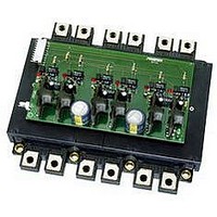
Printed Circuit Layout:
circuit board with only 58 components provides a complete isolated six channel driving circuit with short circuit,
over temperature and under voltage protection. This clearly demonstrates the advantage of using L-Series
Intelligent Power Modules. One important feature of this PCB is the use of separate ground plane islands for
each of the isolated driving circuits, logic level interface, and 24V power supply. Six of the islands are tied to the
common pin of the IPM’s six isolated control power supplies (IPM pins 13, 17, 21, 25, 29, 33). The remaining
two islands are connected at the logic ground (pin 1 of CN1) and 24 VDC power supply ground (pin 1 of CN3)
respectively. This layout is designed to prevent undesirable coupling of noise between the control side and the
floating gate drive channels. The BP6A PCB is designed to plug directly onto the control pins of the L-Series
IPM. This configuration helps to maintain good noise immunity by providing minimal interconnection distance.
More Information:
(1) L-Series IPM individual data sheets provide detailed electrical characteristics of L-Series IPMs
(2) Application Note – “General Considerations: IGBT & IPM modules”, Provides detailed information on power
circuit design including bus bars, snubber circuits and loss calculations. This document also includes heatsink
mechanical requirements and proper mounting procedures.
(3) Application Note – “Introduction to IPMs (Intelligent Power Modules)”, Provides detailed information regarding
features, operational characteristics and interface circuit requirements for Intelligent Power Modules.
(4) BP7A technical data – provides interface circuit information for L-Series IPMs in the low and medium power
“A, B, C” packages.
(5) VLA106-24151 data sheet provides detailed electrical characteristics for the DC to DC converter.
(6) Melcosim loss simulation software - provides quick power loss estimation for L-Series IPMs in three phase
inverter applications.
A typical controller interface for the BP6A is shown in figure 4. The control inputs (W
If the IPM’s built in protection is activated it will immediately shut down the gate drive to the affected IGBT
Figure 5 shows the printed circuit layout of the BG6A interface circuit. The compact 80mm x 140mm
For more information refer to the following documents available from the Powerex website:
5
L
). An on signal (IPM control input
L
) voltage is desired the
N
,V
N
,U
N
,W
P
,V
P
,U
P
)
Related parts for BP6A-L
Image
Part Number
Description
Manufacturer
Datasheet
Request
R

Part Number:
Description:
Manufacturer:
Powerex Inc
Datasheet:
Part Number:
Description:
Manufacturer:
Powerex Inc
Datasheet:
Part Number:
Description:
Manufacturer:
Powerex Inc
Datasheet:
Part Number:
Description:
Manufacturer:
Powerex Inc
Datasheet:
Part Number:
Description:
Manufacturer:
Powerex Inc
Datasheet:
Part Number:
Description:
Manufacturer:
Powerex Inc
Datasheet:
Part Number:
Description:
Manufacturer:
Powerex Inc
Datasheet:
Part Number:
Description:
Manufacturer:
Powerex Inc
Datasheet:
Part Number:
Description:
Manufacturer:
Powerex Inc
Datasheet:
Part Number:
Description:
Manufacturer:
Powerex Inc
Datasheet:
Part Number:
Description:
Manufacturer:
Powerex Inc
Datasheet:
Part Number:
Description:
Manufacturer:
Powerex Inc
Datasheet:
Part Number:
Description:
Manufacturer:
Powerex Inc
Datasheet:
Part Number:
Description:
Manufacturer:
Powerex Inc
Datasheet: