SOUNDBITE Freescale Semiconductor, SOUNDBITE Datasheet - Page 63
SOUNDBITE
Manufacturer Part Number
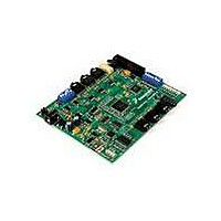
SOUNDBITE
Description
BOARD DEMO AUDIO DEVELOPMENT
Manufacturer
Freescale Semiconductor
Series
Symphony™ soundBiter
Datasheet
1.DSPB56371AF180.pdf
(68 pages)
Specifications of SOUNDBITE
Main Purpose
Audio, Audio Processing
Utilized Ic / Part
DSPB56371
Primary Attributes
Up to 8 channels of digital audio
Secondary Attributes
USB, I2C, SPI Interface
Processor To Be Evaluated
DSP56371
Data Bus Width
24 bit
Interface Type
USB
Lead Free Status / RoHS Status
Lead free / RoHS Compliant
Embedded
-
Lead Free Status / Rohs Status
Lead free / RoHS Compliant


20
20.1 Thermal Design Considerations
An estimation of the chip junction temperature, T
Historically, thermal resistance has been expressed as the sum of a junction-to-case thermal resistance and
a case-to-ambient thermal resistance.
R
change the case-to-ambient thermal resistance, R
the device, add a heat sink, change the mounting arrangement on the printed circuit board (PCB), or
otherwise change the thermal dissipation capability of the area surrounding the device on a PCB. This
model is most useful for ceramic packages with heat sinks; some 90% of the heat flow is dissipated through
the case to the heat sink and out to the ambient environment. For ceramic packages, in situations where
the heat flow is split between a path to the case and an alternate path through the PCB, analysis of the
device thermal performance may need the additional modeling capability of a system level thermal
simulation tool.
The thermal performance of plastic packages is more dependent on the temperature of the PCB to which
the package is mounted. Again, if the estimations obtained from R
the thermal performance is adequate, a system level model may be appropriate.
A complicating factor is the existence of three common ways for determining the junction-to-case thermal
resistance in plastic packages.
Freescale Semiconductor
θJC
•
•
•
is device-related and cannot be influenced by the user. The user controls the thermal environment to
Where:
Where:
To minimize temperature variation across the surface, the thermal resistance is measured from the
junction to the outside surface of the package (case) closest to the chip mounting area when that
surface has a proper heat sink.
To define a value approximately equal to a junction-to-board thermal resistance, the thermal
resistance is measured from the junction to where the leads are attached to the case.
If the temperature of the package case (T
resistance is computed using the value obtained by the equation
(T
Design Considerations
J
– T
T
)/P
T
R
P
D
R
R
R
A
D
.
qJA
θJA
θJC
θCA
=ambient temperature °C
=power dissipation in package W
=package junction-to-ambient thermal resistance °C/W
=package junction-to-case thermal resistance °C/W
=package junction-to-ambient thermal resistance °C/W
=package case-to-ambient thermal resistance °C/W
R θJA
T J
DSP56371 Data Sheet, Rev. 4.1
=
T A
=
+
R θJC
θCA
T
(
P D
J
) is determined by a thermocouple, the thermal
, in °C can be obtained from the following equation:
. For example, the user can change the air flow around
×
+
R θJA
R θCA
)
θJA
do not satisfactorily answer whether
Design Considerations
Eqn. 4
Eqn. 5
63
Related parts for SOUNDBITE
Image
Part Number
Description
Manufacturer
Datasheet
Request
R

Part Number:
Description:
Manufacturer:
Freescale Semiconductor, Inc
Datasheet:
Part Number:
Description:
Manufacturer:
Freescale Semiconductor, Inc
Datasheet:
Part Number:
Description:
Manufacturer:
Freescale Semiconductor, Inc
Datasheet:
Part Number:
Description:
Manufacturer:
Freescale Semiconductor, Inc
Datasheet:
Part Number:
Description:
Manufacturer:
Freescale Semiconductor, Inc
Datasheet:
Part Number:
Description:
Manufacturer:
Freescale Semiconductor, Inc
Datasheet:
Part Number:
Description:
Manufacturer:
Freescale Semiconductor, Inc
Datasheet:
Part Number:
Description:
Manufacturer:
Freescale Semiconductor, Inc
Datasheet:
Part Number:
Description:
Manufacturer:
Freescale Semiconductor, Inc
Datasheet:
Part Number:
Description:
Manufacturer:
Freescale Semiconductor, Inc
Datasheet:
Part Number:
Description:
Manufacturer:
Freescale Semiconductor, Inc
Datasheet:
Part Number:
Description:
Manufacturer:
Freescale Semiconductor, Inc
Datasheet:
Part Number:
Description:
Manufacturer:
Freescale Semiconductor, Inc
Datasheet:
Part Number:
Description:
Manufacturer:
Freescale Semiconductor, Inc
Datasheet:
Part Number:
Description:
Manufacturer:
Freescale Semiconductor, Inc
Datasheet: