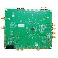
LMK03200EVAL National Semiconductor, LMK03200EVAL Datasheet - Page 20

LMK03200EVAL
Manufacturer Part Number
LMK03200EVAL
Description
BOARD EVALUATION LMK03200
Manufacturer
National Semiconductor
Specifications of LMK03200EVAL
Main Purpose
Timing, Clock Conditioner
Embedded
No
Utilized Ic / Part
LMK03200
Primary Attributes
3 LVDS & 5 LVPECL Outputs, Integrated PLL & VCO
Secondary Attributes
3.15 V ~ 3.45 V Supply
Silicon Manufacturer
National
Silicon Core Number
LMK03200
Kit Application Type
Clock & Timing
Application Sub Type
Precision Clock Conditioner
Kit Contents
Board, Cable
Lead Free Status / RoHS Status
Lead free / RoHS Compliant
Appendix A: Impact of Reference on Phase Noise
Inside the loop bandwidth of a PLL the phase noise is set by the quality of the reference oscillator
used. For this reason it is important to select a reference oscillator suitable for the application.
Power supply noise can also impact the phase noise performance of the oscillator.
T
Using the same loop filter as described in the General Description and by driving the OSCin
frequency with very low jitter 100 MHz Wenzel Crystal (501-04517D) and setting R = 10 to
achieve a phase detector frequency of 10 MHz. A low integrated RMS jitter of 235 fs is measured
vs. the 439 ps measured in the Phase Noise section with 19.44 MHz crystal in the bandwidth of
10 Hz to 20 MHz.
Conclusion
This diagram illustrates how the phase noise inside the loop bandwidth is set by the quality of the
reference oscillator used. Phase noise outside the loop bandwidth is set by the VCO noise level.
est Setup
L M K 0 3 2 0 0
10 Hz – 20 MHz integrated RMS jitter = 235 fs (shown)
100 Hz – 20 MHz integrated RMS jitter = 232 fs
12 kHz – 20 MHz integrated RMS jitter = 210 fs
Figure 18 - Phase Noise with Clean Reference
E V A L U A T I O N
20
B O A R D
O P E R A T I N G
I N S T R U C T I O N S


