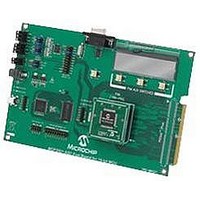
MCP3901EV-MCU16 Microchip Technology, MCP3901EV-MCU16 Datasheet - Page 16

MCP3901EV-MCU16
Manufacturer Part Number
MCP3901EV-MCU16
Description
BOARD EVAL FOR 2CH ADC MCP3901
Manufacturer
Microchip Technology
Datasheets
1.MCP3901A0-ISS.pdf
(60 pages)
2.MCP3901A0-ISS.pdf
(30 pages)
3.MCP3901EV-MCU16.pdf
(38 pages)
4.MCP3901EV-MCU16.pdf
(38 pages)
Specifications of MCP3901EV-MCU16
Number Of Adc's
2
Number Of Bits
24
Data Interface
SPI™
Inputs Per Adc
1 Differential
Input Range
±1 V
Voltage Supply Source
Analog and Digital
Operating Temperature
-40°C ~ 85°C
Utilized Ic / Part
MCP3901
Silicon Manufacturer
Microchip
Application Sub Type
ADC
Kit Application Type
Data Converter
Silicon Core Number
MCP3901, PIC24F, PIC24H, DsPIC33, PIC18F86J55
Kit Contents
Board
Lead Free Status / RoHS Status
Lead free / RoHS Compliant
MCP3901 ADC Evaluation Board for 16-Bit MCUs User’s Guide
2.2
FIGURE 2-1:
DS51845A-page 12
DATA ACQUISITION
Tight to GND CS to select MCP3901
(if true, will follow the reading of
(if true, will follow the reading of
Clear External interrupt 3 Flag
Out of the External Interrupt 3
External interrupt 3 detected
Disable External interrupt 3
The end of a conversion is indicated with a short high pulse on the DR (Data Ready)
pin of the ADC. The DR pin is connected to the External interrupt 3 pin and it is used
for detecting the end of conversion on MCP3901. In the INT3 interrupt, the SPI interrupt
is activated and the first transmission on SPI is initiated. The SPI communication that
follows can be a read of the ADC conversion register or a read of the Configuration
register, to separate the two cases where the CCT global variable will be used: CCT=0
to read ADC conversion, and CCT=1 to read configuration register from MCP3901. It
is possible to read the ADC conversion registers and MCP3901 configuration registers
at the same time, but there will be lots of transfers on the SPI line that will take a lot of
time and this will prevent from achieving a high sampling rate. The SPI communication
is always in an 8-bit mode.
INT3 Flowchart.
The SPI interrupt takes place after each successful data transfer between master and
slave on SPI. As in any interrupt, the first thing to do is to clear the interrupt flag,
otherwise a new interrupt will happen again, for no reason. The CCSPI global value is
the counter that indicates if the SPI transfer that is happening is the first, the second,
etc. After saving the samples into MCU, the SPI communication is disabled by putting
the ADC Configuration
Enable SPI1 Interrupt
Turn ON Red LED
the ADC Results)
Registers)
If cct=0
If cct=1
NO
Send on SPI 0b00001101
(Read Address 6 - ModOut)
YES
YES
(Read Address 0 – CH0 MSB)
Send on SPI 0b00000001
© 2009 Microchip Technology Inc.


