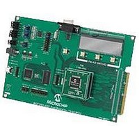
MCP3901EV-MCU16 Microchip Technology, MCP3901EV-MCU16 Datasheet - Page 3

MCP3901EV-MCU16
Manufacturer Part Number
MCP3901EV-MCU16
Description
BOARD EVAL FOR 2CH ADC MCP3901
Manufacturer
Microchip Technology
Datasheets
1.MCP3901A0-ISS.pdf
(60 pages)
2.MCP3901A0-ISS.pdf
(30 pages)
3.MCP3901EV-MCU16.pdf
(38 pages)
4.MCP3901EV-MCU16.pdf
(38 pages)
Specifications of MCP3901EV-MCU16
Number Of Adc's
2
Number Of Bits
24
Data Interface
SPI™
Inputs Per Adc
1 Differential
Input Range
±1 V
Voltage Supply Source
Analog and Digital
Operating Temperature
-40°C ~ 85°C
Utilized Ic / Part
MCP3901
Silicon Manufacturer
Microchip
Application Sub Type
ADC
Kit Application Type
Data Converter
Silicon Core Number
MCP3901, PIC24F, PIC24H, DsPIC33, PIC18F86J55
Kit Contents
Board
Lead Free Status / RoHS Status
Lead free / RoHS Compliant
Preface ........................................................................................................................... 1
Chapter 1. Hardware Description
Chapter 2. Firmware
Chapter 3. MCP3901 PC Software Tool
Appendix A. Schematics and Layouts
© 2009 Microchip Technology Inc.
Introduction............................................................................................................ 1
Document Layout .................................................................................................. 1
Conventions Used in this Guide ............................................................................ 2
Recommended Reading........................................................................................ 3
The Microchip Web Site ........................................................................................ 3
Customer Support ................................................................................................. 3
Document Revision History ................................................................................... 3
1.1 Overview ........................................................................................................ 5
1.2 PIM Module / MCP3901 Connection and Peripheral Usage Overview .......... 7
1.3 MCP3901 Delta-Sigma Sampling / MCLK Options ........................................ 7
1.4 Analog Input Structure .................................................................................... 9
1.5 Universal Serial Bus (USB) ............................................................................ 9
2.1 DSPIC33 Firmware Description ................................................................... 11
2.2 Data Acquisition ........................................................................................... 12
2.3 UART Communication Protocol ................................................................... 14
3.1 Software Overview ....................................................................................... 17
3.2 Setting the Configuration of the ADC ........................................................... 18
3.3 Connectivity and Recording Length ............................................................. 18
3.4 Scope Plot Window - Time Domain Analysis ............................................... 18
3.5 Histogram Window - Noise Analysis ............................................................ 18
3.6 FFT Window - Frequency Domain Analysis ................................................. 19
A.1 Introduction .................................................................................................. 21
A.2 Schematic - Analog ...................................................................................... 22
A.3 Schematic - LCD and UART ....................................................................... 23
A.4 Schematic - USB and Memory ..................................................................... 24
A.5 Schematic - Microcontroller (MCU) .............................................................. 25
A.6 Schematic - PIM Module .............................................................................. 26
A.7 Schematic - Power ....................................................................................... 27
A.8 Board - Top Trace and Top Silk ................................................................... 28
A.9 Board - Bottom Trace and Bottom Silk ........................................................ 28
A.10 Board - Layer #2 VDD ............................................................................... 29
MCP3901 ADC EVALUATION BOARD
Table of Contents
FOR 16-BIT MCUs USER’S GUIDE
DS51845A-page iii


