EVAL-AD7708EBZ Analog Devices Inc, EVAL-AD7708EBZ Datasheet
EVAL-AD7708EBZ
Specifications of EVAL-AD7708EBZ
EVAL-AD7708EB


Related parts for EVAL-AD7708EBZ


EVAL-AD7708EBZ Summary of contents
Page 1
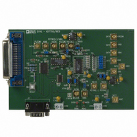
... Full data on the AD7708 is available in the AD7708 datasheet available from Analog Devices and should be consulted in conjunction with this Technical Note when using the evaluation board. The evaluation board interfaces to the parallel port of an IBM compatible PC. Software is available with the evalu- REV. O Information furnished by Analog Devices is believed to be accurate and reliable ...
Page 2
... EVAL-AD7708-EB LINK AND SWITCH OPTIONS There are fifteen link options which must be set for the required operating setup before using the evaluation board. The functions of these link options are outlined below. Link No. Function LK1-LK8 These links are in series with the AIN1 through AIN8 analog inputs respectively. ...
Page 3
... J1 connector is shown in Fig. 3 and its pin designations are given in Table used to connect the evaluation board to the parallel (printer) port of a PC. Connection is via a standard printer cable used to connect the evaluation to any other system. The evaluation board should be powered up before a cable is connected to either of these connectors ...
Page 4
... Ground reference point for digital circuitry. Connects to the DGND plane on the evaluation board. 31- Connect. These pins are not connected on the evaluation board There are eighteen sockets relevant to the operation of the AD7708 on this evaluation board. The functions of these sockets are outlined in Table 4. Table 4. Socket Functions Socket Function J4 9-way D-Type connector used to interface to other systems ...
Page 5
... AD7708 can be operated with internal clock frequencies in the range 32.768 kHz +/- 10 There are two connectors on the AD7718 evaluation board as outlined in Table 5. Table 5. Connector Functions Connector Functions J3 PCB Mounting Terminal Block. The ...
Page 6
... EVAL-AD7708- There is one switch on the AD7708 Evaluation board. SW1 is a push-button reset switch. Pushing this switch activates the active low input on the AD7708 which resets the control logic, interface logic, calibration coefficients, digital filter and analog modulator of the part to power-on status. ...
Page 7
... Allows the user to write the current set of data to a file for later use - user needs to specify single or multi-channel data. About Provides information about the version of software being used. Multi-Channel Test Allows the user to display samples from selected channels at different update rates, polarities and ranges. Quit Ends the program EVAL-AD7708-EB Fig. 4. The Main Screen - 7 - Rev. O ...
Page 8
... EVAL-AD7708-EB The Program AD7708 Screen Fig. 5. shows the screen that appears when the Program AD7708 button is selected. This screen allows the user to select which register programmed. The Filter Register Screen Fig. 6. shows the Filter Register screen. When the screen is loaded the software will read the current contents from the Filter Register of the AD7708 and change the display accordingly ...
Page 9
... Offset Registers are read from the AD7708 and displayed. The user has the ability to change the values of either register if required. the default value for the Fullscale Cal Register is 5xxx hex and the default value for the Zero Scale Cal Register is 8000 hex. EVAL-AD7708- Rev. O ...
Page 10
... EVAL-AD7708-EB The ADC Control Register Screen Fig. 8. shows the ADC Control Register Screen. This register controls Bipolar/Unipolar operation, Channel selection and Range selection for the ADC. When the screen is loaded the software reads the current contents from the ADC Control Register of the AD7708 and sets the buttons accordingly. Note if the Channel Configure bit is set in the Mode Register, the AD7708 channel configuration is changed - see AD7708 datasheets for more information ...
Page 11
... The Mode Register Screen is shown in Fig. 10. When the screen is loaded the software reads the current contents from the Mode Register of the AD7708 and sets the buttons accordingly. This screen allows the user to change the operating mode of the AD7708, change the channel configuration, turn chopping on/off, select the reference EVAL-AD7708- Rev. O ...
Page 12
... EVAL-AD7708-EB voltage and power down the crystal oscillator. When the user selects a calibration the software will start a calibration by writing to the AD7708 (prompt user for input if system calibration) and then monitor the of the pin will indicate that the calibration has been completed. After a calibration the AD7708 is placed in the idle mode and the screen is updated to indicate this ...
Page 13
... It is possible to add a delay to the read cycle by entering the required number of milliseconds between reading samples. It should be noted however that the accuracy of the time delay can be affected by other programs running under Windows, therefore this method is not suitable where equidistant sampling is required. EVAL-AD7708- Rev. O ...
Page 14
... EVAL-AD7708-EB The Noise Analysis Screen Once data has been read from the AD7708 ADC possible to perform some analysis on it. Fig. 13 shows the ADC Noise Analysis Screen. This screen displays the maximum and minimum codes read from the AD7708 ADC (in decimal and hexadecimal), as well as the average code, the average value and the RMS and Peak-Peak noise values. From this screen it is possible to display the data on a graph histogram of codes. Figures 14 & ...
Page 15
... Fig. 14 shows the Graph Screen. This screen displays the data in a graph format. A grid can be placed on the graph by pressing the Grid on/off button. The graph screen also has zoom and scroll functions using the two white handles at either end of the x-axis. EVAL-AD7708-EB Fig. 14. The Graph Screen Fig. 15. The Histogram Screen - 15 - Rev ...
Page 16
... EVAL-AD7708-EB The Multi-Channel Test Screen Fig. 16 shows the Multi-Channel Test Screen. This screen alows the user to select the channels for the multi- channel test. The user can specify range, update rate & polarity for the data. Note if the user selects an pseudo- differential channel, the respective fully-differential channel can't be used ...
Page 17
... Fig. 21. The Evaluation Board Schematic - 17 - EVAL-AD7708-EB Rev. O ...
Page 18
... EVAL-AD7708-EB Table 6. Component Listing and Manufacturers INTEGRATED CIRCUITS Component AD7708 AD780AN 74HC4050N 74C08SMD 74ACT244 SD103C Component 10µF ± 20% Tantalum (16 V) 0.1µF Ceramic (0805 SMD) RESISTORS Component Short Circuits 10k ±5% 0.25W Carbon Film R11-R13 3k ±5% 0.25W Carbon Film LINK OPTIONS ...
Page 19
... Low profile socket U2,U3,U6 CRYSTAL OSCILLATOR Component Location 32.768 kHz Oscillator Xtal 1 Fig. 22. The Evaluation Board Component Layout Diagram EVAL-AD7708-EB Harwin (32 pins needed) Farnell No. 519-959 Vendor FEC No. 221-533 - 19 - Rev. O ...
Page 20
... EVAL-AD7708-EB Fig. 23. The Evaluation Board Component Side Artwork Fig. 23. The Evaluation Board SolderSide Artwork - 20 - Rev. O ...