EVAL-AD7730EBZ Analog Devices Inc, EVAL-AD7730EBZ Datasheet - Page 5
EVAL-AD7730EBZ
Manufacturer Part Number
EVAL-AD7730EBZ
Description
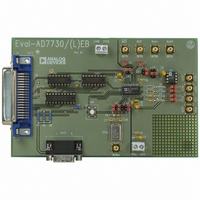
BOARD EVAL FOR AD7730
Manufacturer
Analog Devices Inc
Datasheet
1.EVAL-AD7730EBZ.pdf
(8 pages)
Specifications of EVAL-AD7730EBZ
Number Of Adc's
1
Number Of Bits
24
Sampling Rate (per Second)
1.2k
Data Interface
Serial
Inputs Per Adc
2 Differential
Input Range
±80 mV
Power (typ) @ Conditions
125mW @ 1.2kSPS
Voltage Supply Source
Analog and Digital
Operating Temperature
-40°C ~ 85°C
Utilized Ic / Part
AD7730
Lead Free Status / RoHS Status
Lead free / RoHS Compliant
Other names
EVAL-AD7730EB
EVAL-AD7730EB
EVAL-AD7730EB


SOCKETS
There are eleven sockets on the AD7730 evaluation board. The
function of these sockets is outlined in Table IV.
Socket
SKT1
SKT2
SKT3
SKT4
SKT5
SKT6
SKT7
SKT8
SKT9
SKT10
SKT11
REV. A
Function
9-Way D-Type Connector which can be used for
digital interfacing to the evaluation board.
36-Way Centronics Connector which can be used
for digital interfacing to the evaluation board. This
connector should be used when connecting the
board to the parallel printer port of the PC to use
the evaluation software.
Sub-Minature BNC (SMB) Connector. The analog
input signal for the AIN1(+) input of the AD7730
is applied to this socket.
Sub-Minature BNC (SMB) Connector. The analog
input signal for the AIN1(-) input of the AD7730 is
applied to this socket.
Sub-Minature BNC (SMB) Connector. This socket
provides the ACX ouput from the AD7730.
Sub-Minature BNC (SMB) Connector. This socket
provides the ACX ouput from the AD7730.
Sub-Minature BNC (SMB) Connector. Connects
to the AIN2(-)/D0 pin of the AD7730.
Sub-Minature BNC (SMB) Connector. Connects
to the AIN2(+)/D1 pin of the AD7730.
Sub-Minature BNC (SMB) Connector. The
reference voltage for the REF IN(+) input of the
AD7730 is applied to this socket when the board is
configured for an externally-applied reference
voltage.
Sub-Minature BNC (SMB) Connector. The
reference voltage for the REF IN(-) input of the
AD7730 is applied to this socket when the board is
configured for an externally-applied reference
voltage.
Sub-Minature BNC (SMB) Connector. The master
clock signal for the MCLK IN input of the AD7730
is applied to this socket when the board is
configured for an externally-applied master clock..
Table IV. Socket Functions
–5–
RUNNING THE AD7730 INTERFACE SOFTWARE
Included in the evaluation board package is a PC-compatible
disk which contains software for controlling and evaluating the
performance of the AD7730 using the printer port of a PC.
There are a total of thirteen files on the distribution disk.
To use the software, the user must have an IBM-compatible PC
and Windows 3.1 must be installed. Start Windows and, using
either the RUN command or the File Manager, start the
program called SETUP.EXE on the distribution disk. This
automatically installs the application and sets up a window
called ANALOG DEVICES. The application ICON is found
here. To start the application, double click on the ICON.
When the program starts, the user is asked to select a printer
port. The correct selection depends on what type of computer is
being used (Desktop, Laptop etc). LPT1 works for most
machines. When using a Compaq laptop, select PRN. A
different port can be selected at any time from the MAIN
MENU.
After selecting the printer port, the program displays the Main
Menu as outlined in Figure 4. There are a number of buttons
on the Main Menu which select a variety of different functions.
These are described below.
Program AD7730
Pressing this button calls up a second screen which displays the
contents of the Status Register and provides another set of
buttons allowing the user to program the on-chip registers.
Figure 5 shows the "Program AD7730" screen. Pressing any of
the buttons on this screen pulls up a further screen allowing all
functions in a register to be programmed. Figure 6 gives an
example of one of these screens (the screen for programming the
Mode Register).
Read Data
The Read Data button allows the user access to the "read data"
screen. On this screen, the user can choose whether the reading
of data is for noise analysis or simply for display. It also allows
the user to choose how many outputs of the AD7730 should be
read for the noise analysis routines.
Noise Analysis
The Noise Analysis button gives the user access to the "noise
analysis" screen. Here the user can look at the results of a data
read in terms of rms code distribution, code spread etc. The
user also has the facility to plot the data versus time and plot
histogram results.
Reset AD7730
Pressing this button allows the user access to the reset menu
where either a hardware reset (via the RESET pin) or an
software/interface reset (via writing 32 1's) can be selected. The
user also has a hardware reset button on the board.
EVAL-AD7730EB
Related parts for EVAL-AD7730EBZ
Image
Part Number
Description
Manufacturer
Datasheet
Request
R


Part Number:
Description:
BOARD EVAL FOR SI270X-A
Manufacturer:
Silicon Laboratories Inc
Datasheet:

Part Number:
Description:
BUCK CONV REF DESIGN KIT IP1201
Manufacturer:
International Rectifier
Datasheet:
Part Number:
Description:
BOARD DEMO SYNC DUAL BUCK CNVTER
Manufacturer:
International Rectifier
Datasheet:
Part Number:
Description:
BOARD DEMO SYNC BUCK CONVETER
Manufacturer:
International Rectifier
Datasheet:

Part Number:
Description:
EVALBOARD/EB Omnidirectional microphone - Analog
Manufacturer:
Analog Devices
Datasheet:
Part Number:
Description:
EVALBOARD/EB Omnidirectional microphone - Analog
Manufacturer:
Analog Devices
Datasheet:


Part Number:
Description:
BOARD EVAL LED DRIVER LT3756
Manufacturer:
Linear Technology
Datasheet:

Part Number:
Description:
BOARD EVAL FOR AD7741/7742
Manufacturer:
Analog Devices Inc
Datasheet:

Part Number:
Description:
±1.7g Dual-Axis IMEMS Accelerometer Evaluation Board
Manufacturer:
Analog Devices Inc
Datasheet:

Part Number:
Description:
IC MULTIPLIER ANALOG 8-SOIC T/R
Manufacturer:
Analog Devices Inc
Datasheet:

Part Number:
Description:
IC ANALOG MULTIPLIER 8-DIP
Manufacturer:
Analog Devices Inc
Datasheet:
Part Number:
Description:
IC ANALOG MULTIPLIER 8-SOIC
Manufacturer:
Analog Devices Inc
Datasheet:
Part Number:
Description:
IC ANALOG MULTIPLIER 8-DIP
Manufacturer:
Analog Devices Inc
Datasheet: