ADC101C02XEB/NOPB National Semiconductor, ADC101C02XEB/NOPB Datasheet - Page 18
ADC101C02XEB/NOPB
Manufacturer Part Number
ADC101C02XEB/NOPB
Description
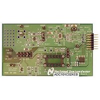
BOARD EVALUATION FOR ADC101C02X
Manufacturer
National Semiconductor
Specifications of ADC101C02XEB/NOPB
Number Of Adc's
1
Number Of Bits
10
Sampling Rate (per Second)
188.9k
Data Interface
I²C
Inputs Per Adc
1 Single Ended
Power (typ) @ Conditions
780mW @ 22kSPS
Voltage Supply Source
Single Supply
Operating Temperature
-40°C ~ 105°C
Utilized Ic / Part
ADC101C021, ADC101C027
Silicon Manufacturer
National
Silicon Core Number
ADC101C021, ADC101C027
Kit Application Type
Data Converter
Application Sub Type
ADC
Kit Contents
Board
Lead Free Status / RoHS Status
Lead free / RoHS Compliant
Other names
ADC101C02XEB


www.national.com
1.6.4 Configuration Register
Pointer Address 02h (Read/Write)
Default Value: 00h
1.6.5 V
This register holds the lower limit threshold used to determine the alert condition. If the conversion moves lower than this limit, a
V
Pointer Address 03h (Read/Write)
Default Value: 0000h
Cycle Time [2:0]
Bits
7:5
4
3
2
1
0
Bits
15:12
11:2
1:0
D7
D7
LOW
0
Cycle Time[2:0]
D15
alert is generated.
D7
D6
LOW
D6
0
Name
Cycle Time
Alert Hold
Alert Flag Enable
Alert Pin Enable
Reserved
Polarity
Name
Reserved
V
Reserved
LOW
-- Alert Limit Register - Under Range
D5
Limit
D5
0
Alert
Hold
D4
D14
D6
Enable
Mode Disabled
Reserved
Alert
Flag
Conversion
D3
Interval
Description
Configures Automatic Conversion mode. When these bits are set to zeros, the automatic
conversion mode is disabled. This is the case at power-up.
When these bits are set to a non-zero value, the ADC will begin operating in automatic conversion
mode. (See Section 1.9 AUTOMATIC CONVERSION MODE). The Cycle Time table shows how
different values provide various conversion intervals.
0: Alerts will self-clear when the measured voltage moves within the limits by more than the
hysteresis register value.
1: Alerts will not self-clear and are only cleared when a one is written to the alert high flag or the
alert low flag in the Alert Status register.
0: Disables alert status bit [D15] in the Conversion Result register.
1: Enables alert status bit [D15] in the Conversion Result register.
0: Disables the ALERT output pin. The ALERT output will TRI-STATE when the pin is disabled.
1: Enables the ALERT output pin.
*This bit does not apply to the ADC101C027.
Always reads zeros. Zeros must be written to these bits.
This bit configures the active level polarity of the ALERT output pin.
0: Sets the ALERT pin to active low.
1: Sets the ALERT pin to active high.
*This bit does not apply to the ADC101C027.
Description
Always reads zeros. Zeros must be written to these bits.
Sets the lower limit threshold used to determine the alert condition. If the conversion moves lower
than this limit, a V
Always reads zeros. Zeros must be written to these bits.
Enable
Alert
Pin
D13
D2
D5
V
LOW
Limit [5:0]
D1
0
Typical
f
(ksps)
LOW
convert
Polarity
0
D12
D4
D0
alert is generated.
18
0
0
0
1
1
1
1
D11
D3
0
1
1
0
0
1
1
1
0
1
0
1
0
1
D10
D2
V
LOW
Limit [9:6]
T
T
T
T
T
T
T
convert
convert
convert
convert
convert
convert
convert
x 1024
x 2048
D9
D1
x 128
x 256
x 512
x 32
x 64
Reserved
D8
D0
13.5
6.7
3.4
1.7
0.9
0.4
27
Related parts for ADC101C02XEB/NOPB
Image
Part Number
Description
Manufacturer
Datasheet
Request
R

Part Number:
Description:
National Semiconductor [8-Bit D/A Converter]
Manufacturer:
National Semiconductor
Datasheet:
Part Number:
Description:
National Semiconductor [Media Coprocessor]
Manufacturer:
National Semiconductor
Datasheet:
Part Number:
Description:
Digitally Controlled Tone and Volume Circuit with Stereo Audio Power Amplifier, Microphone Preamp Stage and National 3D Sound
Manufacturer:
National Semiconductor
Datasheet:
Part Number:
Description:
Digitally Controlled Tone and Volume Circuit with Stereo Audio Power Amplifier, Microphone Preamp Stage and National 3D Sound
Manufacturer:
National Semiconductor
Datasheet:
Part Number:
Description:
AC97 Rev 2 Codec with Sample Rate Conversion and National 3D Sound
Manufacturer:
National Semiconductor
Part Number:
Description:
Manufacturer:
National Semiconductor
Datasheet:
Part Number:
Description:
Manufacturer:
National Semiconductor
Datasheet:
Part Number:
Description:
General Purpose, Low Voltage, Low Power, Rail-to-Rail Output Operational Amplifiers
Manufacturer:
National Semiconductor
Datasheet:
Part Number:
Description:
8-bit 20 MSPS flash A/D converter.
Manufacturer:
National Semiconductor
Datasheet:
Part Number:
Description:
Low Noise Quad Operational Amplifier
Manufacturer:
National Semiconductor
Datasheet:
Part Number:
Description:
Quad Differential Line Receivers
Manufacturer:
National Semiconductor
Datasheet:
Part Number:
Description:
Quad High Speed Trapezoidal? Bus Transceiver
Manufacturer:
National Semiconductor
Datasheet:
Part Number:
Description:
Dual Line Receiver
Manufacturer:
National Semiconductor
Datasheet:
Part Number:
Description:
TTL to 10k ECL Level Translator with Latch
Manufacturer:
National Semiconductor
Datasheet: