SSM2317-MINI-EVALZ Analog Devices Inc, SSM2317-MINI-EVALZ Datasheet

BOARD EVAL MINI SSM2317

SSM2317-MINI-EVALZ

Manufacturer Part Number
SSM2317-MINI-EVALZ
Description
BOARD EVAL MINI SSM2317
Manufacturer
Analog Devices Inc

Specifications of SSM2317-MINI-EVALZ

Amplifier Type
Class D
Output Type
1-Channel (Mono)
Max Output Power X Channels @ Load
3.89W x 1 @ 3 Ohm
Voltage - Supply
2.5 V ~ 5.5 V
Operating Temperature
-40°C ~ 85°C
Board Type
Fully Populated
Utilized Ic / Part
SSM2317
Silicon Manufacturer
Analog Devices
Application Sub Type
Audio Power Amplifier - Class D
Kit Application Type
Amplifier
Silicon Core Number
SSM2317
Kit Contents
Board
Lead Free Status / RoHS Status
Lead free / RoHS Compliant
FEATURES
Single-ended and differential input capability
Small size board allows easy integration into custom
GENERAL DESCRIPTION
The SSM2317 is a fully integrated, single-chip, mono Class-D
audio amplifier. It is designed to maximize performance for
mobile phone applications. The application circuit requires a
minimum of external components and operates from a single
2.5 V to 5.5 V supply. It is capable of delivering 1.4 W of con-
tinuous output power with less than 1% THD + N, driving an
8 Ω load from a single 5.0 V supply.
The SSM2317 is equipped with a differential mode input port
and a high efficiency, full H-bridge at the output that enables
direct coupling of the audio power signal to the loudspeaker.
The differential mode input stage allows for cancelling of
common-mode noise.
The part also features a high efficiency, low noise output
modulation scheme that does not require external LC output
filters when attached to an inductive load. It operates with
85% efficiency at 1.4 W into 8 Ω from a 5.0 V supply and has
a signal-to-noise ratio (SNR) that is better than 93 dB.
Rev. 0
Evaluation boards are only intended for device evaluation and not for production purposes.
Evaluation boards are supplied “as is” and without warranties of any kind, express, implied, or
statutory including, but not limited to, any implied warranty of merchantability or fitness for a
particular purpose. No license is granted by implication or otherwise under any patents or other
intellectual property by application or use of evaluation boards. Information furnished by Analog
Devices is believed to be accurate and reliable. However, no responsibility is assumed by Analog
Devices for its use, nor for any infringements of patents or other rights of third parties that may
result from its use. Analog Devices reserves the right to change devices or specifications at any
time without notice. Trademarks and registered trademarks are the property of their respective
owners. Evaluation boards are not authorized to be used in life support devices or systems.
space-constrained applications (6.6 mm × 6.6 mm)
Figure 1. SSM2317 Evaluation Board Top View
Filterless Class-D Audio Amplifier
One Technology Way, P.O. Box 9106, Norwood, MA 02062-9106, U.S.A.
Tel: 781.329.4700
Fax: 781.461.3113
Spread-spectrum modulation is used to provide lower EMI-
radiated emissions. The modulation provides high efficiency
even at low output power. Filterless operation also helps to
decrease distortion due to the nonlinearities of output LC filters.
This data sheet describes how to configure and use the SSM2317
mini evaluation board to test the SSM2317. It is recommended
that this data sheet be read in conjunction with the
data sheet, which provides more detailed information about
the specifications, internal block diagrams, and application
guidance for the amplifier IC.
EVALUATION BOARD DESCRIPTION
The SSM2317 mini evaluation board is a small form factor
board (6.6 mm × 6.6 mm) with a pair of differential audio
input terminals (IN+ and IN−), a pair of audio signal output
terminals (OUT+ and OUT−), a ground terminal, and a VDD
terminal. It is designed for easy integration into the SSM2317
application board.
The SSM2317 mini evaluation board carries a complete
application circuit for driving a loudspeaker. Figure 1 shows
the top view of the evaluation board, and Figure 2 shows the
bottom view.
Figure 2. SSM2317 Evaluation Board Bottom View
EVAL-SSM2317-MINI
Evaluation Board for
©2009 Analog Devices, Inc. All rights reserved
www.analog.com
SSM2317
.

Related parts for SSM2317-MINI-EVALZ

SSM2317-MINI-EVALZ Summary of contents

Page 1

... The modulation provides high efficiency even at low output power. Filterless operation also helps to decrease distortion due to the nonlinearities of output LC filters. This data sheet describes how to configure and use the SSM2317 mini evaluation board to test the SSM2317 recommended that this data sheet be read in conjunction with the ...

Page 2

... EVAL-SSM2317-MINI TABLE OF CONTENTS Features .............................................................................................. 1 General Description ......................................................................... 1 Evaluation Board Description ......................................................... 1 Revision History ............................................................................... 2 Evaluation Board Hardware ............................................................ 3 Input and Output Configuration ................................................ 3 Component Selection................................................................... 3 REVISION HISTORY 5/09—Revision 0: Initial Version   PCB Layout Guidelines .................................................................4   Getting Started ...............................................................................4   Evaluation Board Schematic and Artwork .....................................5   Ordering Information .......................................................................8   ...

Page 3

... Although the SSM2317 does not require external LC output filters to operate because it has a low noise modulation scheme, if the speaker length is >10 cm recommended to put a ferrite bead (L1 and L2) near each output pin of the SSM2317 to reduce electromagnetic interference (EMI), as shown in the schematic in Figure 3. For optimal performance, as specified ...

Page 4

... Bottom layer—bottom layer with ground copper pouring. Component Placement and Clearance Place all related components except decoupling capacitors on the same side as the SSM2317 to avoid vias and as close as possible to the chip (see Figure 4). Place the decoupling capacitors, C5 and C7, on the bottom side as close as possible to the VDD and GND pins (see Figure 5) ...

Page 5

... VDD C5 C7 10µF 0.1µF 1B IN+ OUT SSM2317 0.1µF 1A IN– OUT– C2 0.1µF R3 6.98kΩ VDD R1 100kΩ G1 VDD R2 GAP 100kΩ Figure 3. Schematic of the SSM2317-MINI Evaluation Board Rev Page EVAL-SSM2317-MINI B0603 OUT 1nF 1nF B0603 OUT– P4 ...

Page 6

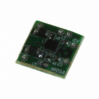
... EVAL-SSM2317-MINI Figure 4. Top Layer with Top Silkscreen Figure 5. Bottom Layer with Bottom Silkscreen (Mirror Image) Figure 6. Top Silkscreen Figure 7. Top Layer Figure 8. Top Layer Figure 9. Layer 2 (Ground Plane) Rev Page ...

Page 7

... Figure 10. Layer 3 (Power Plane) Figure 11. Bottom Layer Figure 12. All Layer Silkscreen Rev Page EVAL-SSM2317-MINI ...

Page 8

... R1 ORDERING GUIDE Model Description 1 SSM2317-MINI-EVALZ Evaluation Board RoHS Compliant Part. ©2009 Analog Devices, Inc. All rights reserved. Trademarks and registered trademarks are the property of their respective owners. Description Ceramic capacitor, 0.1 μF, 6.3 V Ceramic capacitor, 1 nF, 10 Ceramic capacitor, 10 μ GAP Ferrite chip, B0603, 220 Ω ...

Related keywords