SSM2317-MINI-EVALZ Analog Devices Inc, SSM2317-MINI-EVALZ Datasheet - Page 4
SSM2317-MINI-EVALZ
Manufacturer Part Number
SSM2317-MINI-EVALZ
Description
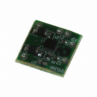
BOARD EVAL MINI SSM2317
Manufacturer
Analog Devices Inc
Specifications of SSM2317-MINI-EVALZ
Amplifier Type
Class D
Output Type
1-Channel (Mono)
Max Output Power X Channels @ Load
3.89W x 1 @ 3 Ohm
Voltage - Supply
2.5 V ~ 5.5 V
Operating Temperature
-40°C ~ 85°C
Board Type
Fully Populated
Utilized Ic / Part
SSM2317
Silicon Manufacturer
Analog Devices
Application Sub Type
Audio Power Amplifier - Class D
Kit Application Type
Amplifier
Silicon Core Number
SSM2317
Kit Contents
Board
Lead Free Status / RoHS Status
Lead free / RoHS Compliant


EVAL-SSM2317-MINI
PCB LAYOUT GUIDELINES
To keep the EMI under the allowable limit and ensure that the
amplifier chip operates under the temperature limit, PCB layout
is critical in application design. The SSM2317 works well only if
the following techniques are implemented in the PCB design to
keep EMI and the amplifier temperature low.
Layer Stacks and Grounding
Use a 4-layer structure in the stack-up for the evaluation board,
as follows:
•
•
•
•
Component Placement and Clearance
Place all related components except decoupling capacitors on
the same side as the SSM2317 to avoid vias and as close as
possible to the chip (see Figure 4).
Place the decoupling capacitors, C5 and C7, on the bottom side
as close as possible to the VDD and GND pins (see Figure 5).
Place the C3 and C4 capacitors and the R1 pull-up resistor on
the bottom layer (see Figure 5).
Traces and Solder Resist
All traces between adjacent pads must be covered with solder
resist. Traces should come symmetrically off the pads.
Top layer—component layer with power and output copper
land and ground copper pouring.
Second layer—dedicated ground plane.
Third layer—dedicated power plane.
Bottom layer—bottom layer with ground copper pouring.
Rev. 0 | Page 4 of 8
Use 5 mils traces at the SSM2317 pads to prevent the solder
from escaping.
Top Layer Copper Land and Ground Pouring
The output peak current of this amplifier is more than 1 A;
therefore, PCB traces should be wide (>2 mm) to handle high
current. For the best performance, use symmetrical copper
lands as large as space allows, instead of traces for output pins
(see Figure 3).
Pour ground copper on the top side and use many vias to
connect the top layer ground copper to the dedicated ground
plane. The copper pouring land on the top layer serves as both
the EMI shielding ground plane and the heat sink for the
SSM2317.
Power Land
Connect Pin B2 directly to Pin A2 by a 5 mil trace and make a
copper land for the power near A2. If space allows, use four
12/24 mil vias to connect the top layer power land to the
dedicated power plane (Layer 3).
GETTING STARTED
To ensure proper operation, carefully follow Step 1 through Step 3.
1.
2.
3.
Connect the load to the audio output terminals, OUT+ and
OUT−.
Connect the audio input to the audio input terminals, IN+
and IN−.
Connect the power supply to VDD and GND.
Related parts for SSM2317-MINI-EVALZ
Image
Part Number
Description
Manufacturer
Datasheet
Request
R

Part Number:
Description:
BOARD EVAL SSM2317
Manufacturer:
Analog Devices Inc
Datasheet:

Part Number:
Description:
Filterless High Efficiency Mono 3 W Class-d Audio Amplifier
Manufacturer:
Analog Devices, Inc.
Datasheet:

Part Number:
Description:
±1.7g Dual-Axis IMEMS Accelerometer Evaluation Board
Manufacturer:
Analog Devices Inc
Datasheet:

Part Number:
Description:
Inertial Sensor Evaluation System
Manufacturer:
Analog Devices Inc
Datasheet:
Part Number:
Description:
Manufacturer:
Analog Devices Inc
Datasheet:
Part Number:
Description:
Manufacturer:
Analog Devices Inc
Datasheet:
Part Number:
Description:
Manufacturer:
Analog Devices Inc
Datasheet:
Part Number:
Description:
Manufacturer:
Analog Devices Inc
Datasheet:
Part Number:
Description:
Manufacturer:
Analog Devices Inc
Datasheet:
Part Number:
Description:
Manufacturer:
Analog Devices Inc
Datasheet:
Part Number:
Description:
Manufacturer:
Analog Devices Inc
Datasheet:
Part Number:
Description:
Manufacturer:
Analog Devices Inc
Datasheet:
Part Number:
Description:
Manufacturer:
Analog Devices Inc
Datasheet: