CRD3511-Q1 Cirrus Logic Inc, CRD3511-Q1 Datasheet
CRD3511-Q1
Specifications of CRD3511-Q1


Related parts for CRD3511-Q1


CRD3511-Q1 Summary of contents
Page 1
... A, deliver high efficiency, allow a small device package, and lower power supply voltage levels. The CS3511 is available in a 32-pin QFN package in Commercial grade (-10°C to +70°C). The CRD3511 customer reference design is also available. Please re- fer to “Ordering Information” on page 25 ordering information ...
Page 2
TABLE OF CONTENTS 1. PIN DESCRIPTIONS .............................................................................................................................. 4 2. CHARACTERISTICS AND SPECIFICATIONS ...................................................................................... 6 RECOMMENDED OPERATING CONDITIONS .................................................................................... 6 ABSOLUTE MAXIMUM RATINGS ........................................................................................................ 6 AC ELECTRICAL CHARACTERISTICS ................................................................................................ 7 DC ELECTRICAL CHARACTERISTICS ................................................................................................ 9 DIGITAL INTERFACE SPECIFICATIONS ............................................................................................. 9 DIGITAL ...
Page 3
LIST OF FIGURES Figure 1.Typical Connection Diagram - Stereo Amplifier with Differential Inputs ...................................... 11 Figure 2.Typical Connection Diagram - Stereo Amplifier with Single-Ended Inputs ................................. 12 Figure 3.CS3511 Input Stage .................................................................................................................... 13 Figure 4.Output Filter ................................................................................................................................ 16 Figure 5.THD+N ...
Page 4
PIN DESCRIPTIONS IN1+ V5D GAIN0 DGND REF SLEEP MUTE STATUS # Pin Name Pin Description IN1+ 1 IN1- 32 Differential Analog Input (Input) - Differential Audio Signal Inputs for channel 1 and channel 2. IN2+ 24 IN2- 25 V5D ...
Page 5
OUT1+ 9 OUT1- 12 Differential PWM Output (Output) - Differential PWM Outputs for channel 1 and channel 2. OUT2+ 16 OUT2 High Voltage Power (Input) - Supply pins for high current H-bridges PGND 14 ...
Page 6
CHARACTERISTICS AND SPECIFICATIONS RECOMMENDED OPERATING CONDITIONS AGND = DGND = PGND = 0 V; All voltages with respect to ground. Parameters DC Power Supply Supply Voltage Temperature Ambient Temperature Junction Temperature Notes: 1. Device functionality is not guaranteed or ...
Page 7
AC ELECTRICAL CHARACTERISTICS Test Conditions (unless otherwise specified): AGND = DGND = PGND = 0 V; All voltages with respect to ground Ω full-bridge; GAIN1 = 0, GAIN0 = kHz Measurement Bandwidth; Per- ...
Page 8
Parameters General Specifications Efficiency Gain Matching Power Supply Rejection Ratio IHF Intermodulation Distortion Input Impedance Output Offset Voltage (Note 10) PWM Output Over-Current Error Trigger Point Junction Thermal Error Rising Trigger Point Junction Thermal Error Falling Trigger Point Turn On ...
Page 9
DC ELECTRICAL CHARACTERISTICS Test Conditions (unless otherwise specified): AGND = DGND = PGND = 0 V; All voltages with respect to ground Ω full-bridge; GAIN1 = 0, GAIN0 = 1; Stereo Full-Bridge measurements taken T = 25°C; VP ...
Page 10
DIGITAL I/O PIN CHARACTERISTICS The logic level for each input is set by its corresponding power supply and should not exceed the maximum ratings. Power Pin Pin Name Supply Number 3 GAIN0 22 GAIN1 5VD 7 MUTE 6 SLEEP 8 ...
Page 11
TYPICAL CONNECTION DIAGRAMS System Control Logic 1.0 µf R1 Differential 1.0 µf Analog Inputs R2 Note(R1=R2) 1.0 µf R3 Differential 1.0 µf Analog Inputs R4 Note(R3=R4) 10 µf 10 µf 1 µf 1 µ (Note 2) 0.1 ...
Page 12
System Control 7 Logic 1.0 µ Single-Ended 1.0 µf Analog Input R2 32 Note(R1=R2) Important: See (Note 3) 1.0 µ Single-Ended 1.0 µf Analog Input R4 25 Note(R3=R4 ...
Page 13
APPLICATIONS 4.1 CS3511 Input Stage The input stage of the CS3511 is configured as a differential receiver to maximize common-mode rejection in typical audio circuits. To maximize this benefit, the INx+ and INx- pins should be driven with differential ...
Page 14
... the CRD3511, a value of 1.0 µF is used for C even for the highest gain setting. In many cases, a lower value because the speakers used do not have the ability to reproduce low-frequency signals. 4.4 MUTE Pin The MUTE pin must be driven to a logic low or logic high state for proper operation. To enable the amplifier, connect the MUTE pin to a logic low ...
Page 15
Recommended Power-Down Sequence 1. Set the MUTE pin to the logic high state. This will mute the amplifier outputs and hold them in a high- impedance state. 2. Optionally, the SLEEP pin can now be set to a logic ...
Page 16
... CS3511 amplifier’s switching pattern will degrade the measurement result. One feature of the CS3511 is that it does not require large multi-pole filters to achieve excellent performance in listening tests, usually a more critical factor than performance measurements. The CRD3511 Evaluation Board uses the filter described in formance in listening tests ...
Page 17
... PCB layers; the copper in these ground planes will act as a heat sink for the CS3511. The CRD3511 reference design demonstrates the optimum thermal pad and via configuration. ...
Page 18
... TYPICAL AUDIO PERFORMANCE PLOTS Test Conditions (unless otherwise specified): All plots were taken using the CRD3511 Reference Design Board sourced with a differential input taken with a 997 Hz sine wave and AES17 measurement filter; GAIN1 = 0, GAIN0 = VDC 0.5 % 0.2 0.1 0.05 0.02 0.01 ...
Page 19
... Figure 13. THD+N vs. Frequency ( 100 200 500 1k Hz Figure 15. Frequency Response (P Note: The full-bridge output filter found on the CRD3511 reference design board implements 22µH inductors and is optimized for an 8 Ω load. DS845F1 2.5 2 1 Ω) (R Figure 12. Supply Current vs. P OUT 0.5 5 ...
Page 20
CH2 to CH1 B -100 -120 CH1 to CH2 -140 20 50 100 200 500 1k Hz Figure 17. Crosstalk vs. Frequency (R +20 +0 -20 - -60 V -80 -100 -120 -140 20 ...
Page 21
Output Power Per Channel (Watts) Figure 23. Efficiency (R DS845F1 100 ...
Page 22
PARAMETER DEFINITIONS Signal to Noise Ratio (SNR) The ratio of the RMS value of the output signal, where Pout is equivalent to the specified output power at THD+N<1%, to the RMS value of the noise floor with no input ...
Page 23
PACKAGE DIMENSIONS 32L QFN ( BODY) PACKAGE DRAWING D Pin #1 Corner Top View INCHES DIM MIN A 0.031 A1 0. 0.008 REF b 0.008 D - 0.2362 BSC D2 0.177 E 0.2362 BSC ...
Page 24
THERMAL CHARACTERISTICS Parameter Junction to Case Thermal Impedance 9.1 Thermal Flag This device is designed to have the metal flag on the bottom of the device soldered directly to a metal plane on the PCB. To enhance the thermal ...
Page 25
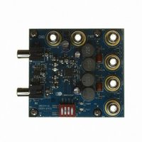
... INFORMATION Product Description Stereo, 10W High-Efficiency CS3511 Class-D Audio Amplifier Layer / 1 oz. CRD3511-Q1 Copper Reference Design DS845F1 Package Pb-Free Grade Temp Range Container 32-QFN Yes Commercial -10° to +70° CS3511 Order# Rail CS3511-CNZ Tape and CS3511-CNZR Reel - - CRD3511-Q1 25 ...
Page 26
HISTORY Release F1 – Updated Channel Separation on front page. – Updated Output Power, Channel Separation, and Efficiency specifications in Characteristics” table on page – Added Single Ended performance data in the – Updated 5VGEN DC Current Source specification ...