MCP1640EV-SBC Microchip Technology, MCP1640EV-SBC Datasheet
MCP1640EV-SBC
Specifications of MCP1640EV-SBC
Available stocks


Related parts for MCP1640EV-SBC


MCP1640EV-SBC Summary of contents
Page 1
... Synchronous Boost Converter 2010 Microchip Technology Inc. MCP1640 Evaluation Board User’s Guide DS51880A ...
Page 2
... PICtail, REAL ICE, rfLAB, Select Mode, Total Endurance, TSHARC, UniWinDriver, WiperLock and ZENA are trademarks of Microchip Technology Incorporated in the U.S.A. and other countries. SQTP is a service mark of Microchip Technology Incorporated in the U.S.A. All other trademarks mentioned herein are property of their respective companies. ...
Page 3
... A.3 Board – Top Silk and Pads .......................................................................... 17 A.4 Board – Top Copper Layer .......................................................................... 18 A.5 Board – Bottom Copper Layer ..................................................................... 19 Appendix B. Bill of Materials (BOM) Worldwide Sales and Service .................................................................................... 22 2010 Microchip Technology Inc. MCP1640 SYNCHRONOUS BOOST CONVERTER EVALUATION BOARD Table of Contents USER’S GUIDE ...
Page 4
... MCP1640 Synchronous Boost Converter Evaluation Board User’s Guide NOTES: DS51880A-page 4 2010 Microchip Technology Inc. ...
Page 5
... Appendix A. “Schematic and Layouts” – Shows the schematic and layout diagrams for the MCP1640 Synchronous Boost Converter Evaluation Board. • Appendix B. “Bill of Materials (BOM)” – Lists the parts used to build the MCP1640 Synchronous Boost Converter Evaluation Board. 2010 Microchip Technology Inc. MCP1640 SYNCHRONOUS BOOST CONVERTER EVALUATION BOARD Preface NOTICE TO CUSTOMERS USER’ ...
Page 6
... Optional arguments mcc18 [options] file [options] Choice of mutually exclusive errorlevel {0|1} arguments selection Replaces repeated text var_name [, var_name...] Represents code supplied by void main (void) user { ... } 2010 Microchip Technology Inc. Examples ® IDE User’s Guide ...
Page 7
... Customers should contact their distributor, representative or field application engineer (FAE) for support. Local sales offices are also available to help customers. A listing of sales offices and locations is included in the back of this document. Technical support is available through the web site at: http://support.microchip.com 2010 Microchip Technology Inc. Preface DS51880A-page 7 ...
Page 8
... MCP1640 Synchronous Boost Converter Evaluation Board User’s Guide DOCUMENT REVISION HISTORY Revision A (February 2010) • Initial Release of this Document. DS51880A-page 8 2010 Microchip Technology Inc. ...
Page 9
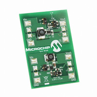
... EVALUATION BOARD? The MCP1640 Synchronous Boost Converter Evaluation Board is used to evaluate and demonstrate Microchip Technology’s MCP1640 products. This board demonstrates the MCP1640 in two boost-converter applications with multiple output voltages. It can be used to evaluate both package options (SOT-23-6 and 2x3-8 DFN). The MCP1640 Synchronous Boost Converter Evaluation Board was developed to help engineers reduce the product design cycle time ...
Page 10
... For more information on these options, refer to the MCP1640/B/C/D datasheet. 1.3 CONTENTS OF THE MCP1640 SYNCHRONOUS BOOST CONVERTER EVALUATION BOARD This MCP1640 Synchronous Boost Converter Evaluation Board kit includes: • One MCP1640 Synchronous Boost Converter Evaluation Board unit, 102-00283 • Important Information "Read First" DS51880A-page 10 2010 Microchip Technology Inc. ...
Page 11
... V The MCP1640 is available in SOT-23-6 and 2x3 mm DFN-8 lead packages. 2010 Microchip Technology Inc. MCP1640 SYNCHRONOUS BOOST CONVERTER EVALUATION BOARD ...
Page 12
... As an example, the MCP1640 can typically supply a 3.3V load with 100 mA with a 1.2V input. DS51880A-page 12 : 0.35V to 5.5V, with V load after startup IN IN OUT = 1.2V 3.3V and I IN OUT OUT 2010 Microchip Technology Inc. = 1mA, resistive load ...
Page 13
... OFF Note that SW2 (V SW1 (V SEL) and SW3 (EN) are used for the 2x3 mm DFN-8 circuit. OUT 2010 Microchip Technology Inc. Installation and Operation and GND terminals, maximum load varies with OUT OUT and GND terminals. When EN is low, the MCP1640 is disabled and ...
Page 14
... SEL switch in the open or OFF position, the output voltage can be calculated OUT using the following equation: Where: The V Note: DS51880A-page 14 SETTING OUT V OUT ------------ - OUT ------------ - 1.21V FB SELL switch will not be used. OUT – 1 – 1 2010 Microchip Technology Inc. ...
Page 15
... Synchronous Boost Converter Evaluation Board: • Board – Schematic • Board – Top Silk and Pads • Board – Top Copper Layer • Board – Bottom Copper Layer 2010 Microchip Technology Inc. MCP1640 SYNCHRONOUS BOOST CONVERTER EVALUATION BOARD USER’S GUIDE DS51880A-page 15 ...
Page 16
... MCP1640 Synchronous Boost Converter Evaluation Board User’s Guide A.2 BOARD – SCHEMATIC DS51880A-page 16 2010 Microchip Technology Inc. ...
Page 17
... A.3 BOARD – TOP SILK AND PADS 2010 Microchip Technology Inc. Schematic and Layouts DS51880A-page 17 ...
Page 18
... MCP1640 Synchronous Boost Converter Evaluation Board User’s Guide A.4 BOARD – TOP COPPER LAYER DS51880A-page 18 2010 Microchip Technology Inc. ...
Page 19
... A.5 BOARD – BOTTOM COPPER LAYER 2010 Microchip Technology Inc. Schematic and Layouts DS51880A-page 19 ...
Page 20
... MCP1640 Synchronous Boost Converter Evaluation Board User’s Guide NOTES: DS51880A-page 20 2010 Microchip Technology Inc. ...
Page 21
... U2 MCP1640 Syncronous Boost Converter – DFN2x3mm The components listed in this Bill of Materials are representative of the PCB assembly. The Note 1: released BOM used in manufacturing uses all RoHS-compliant components. 2010 Microchip Technology Inc. MCP1640 SYNCHRONOUS BOOST CONVERTER EVALUATION BOARD Description Manufacturer 3M Murata Electronics North America — ...
Page 22
... Fax: 886-3-6578-370 Taiwan - Kaohsiung Tel: 886-7-536-4818 Fax: 886-7-536-4803 Taiwan - Taipei Tel: 886-2-2500-6610 Fax: 886-2-2508-0102 Thailand - Bangkok Tel: 66-2-694-1351 Fax: 66-2-694-1350 2010 Microchip Technology Inc. EUROPE Austria - Wels Tel: 43-7242-2244-39 Fax: 43-7242-2244-393 Denmark - Copenhagen Tel: 45-4450-2828 Fax: 45-4485-2829 France - Paris Tel: 33-1-69-53-63-20 ...