MCP1640EV-SBC Microchip Technology, MCP1640EV-SBC Datasheet - Page 9
MCP1640EV-SBC
Manufacturer Part Number
MCP1640EV-SBC
Description
BOARD EVAL FOR MCP1640
Manufacturer
Microchip Technology
Type
DC/DC Switching Converters, Regulators & Controllersr
Datasheets
1.MCP1640CT-ICHY.pdf
(32 pages)
2.MCP1640CT-ICHY.pdf
(26 pages)
3.MCP1640EV-SBC.pdf
(22 pages)
Specifications of MCP1640EV-SBC
Main Purpose
DC/DC, Step Up
Outputs And Type
1, Non-Isolated
Voltage - Output
2V, 3.3V or 5V
Current - Output
100mA, 350mA
Voltage - Input
0.35 ~ 5.5V
Regulator Topology
Boost
Frequency - Switching
500kHz
Board Type
Fully Populated
Utilized Ic / Part
MCP1640
Input Voltage
0.35 V to 5.5 V
Output Voltage
3.3 V to 5 V
Operating Supply Voltage
0.35 V to 5.5 V
Product
Power Management Modules
Supply Current
300 mA
Kit Contents
Board
Features
Automatic PFM/PWM Operation, Enable State Selectable Using Mini-Dip Switch On Board
Svhc
No SVHC (15-Dec-2010)
Core Architecture
Power Management - Voltage Regulator
Rohs Compliant
Yes
For Use With/related Products
MCP1640
Lead Free Status / RoHS Status
Contains lead / RoHS non-compliant
Power - Output
-
Lead Free Status / Rohs Status
Lead free / RoHS Compliant
Available stocks
Company
Part Number
Manufacturer
Quantity
Price
Company:

Part Number:
MCP1640EV-SBC
Manufacturer:
Microchip Technology
Quantity:
135
Company:
Part Number:
MCP1640EV-SBC
Manufacturer:
MICROCHIP
Quantity:
12 000


1.1
1.2
2010 Microchip Technology Inc.
INTRODUCTION
WHAT IS THE MCP1640 SYNCHRONOUS BOOST CONVERTER
EVALUATION BOARD?
The MCP1640 is a compact, high-efficiency, fixed frequency, step-up DC-DC converter.
It provides an easy-to-use power supply solution, with a minimum number of external
components for applications powered by one-cell, two-cell, or three-cell alkaline, NiCd,
NiMH, one-cell Li-Ion or Li-Polymer batteries.
The MCP1640 automatically selects the best operating mode for efficiency, Pulse
Width Modulation (PWM) or Pulse Frequency (PFM); it has a low quiescent current
(20 µA), a wide input voltage range (0.35 to 5.5V) and low start-up voltage (0.65V).
The MCP1640 is available in SOT-23-6 and 2x3mm-8 DFN packages.
This chapter provides an overview of the MCP1640 Boost Controller Evaluation Board
and covers the following topics:
• What is the MCP1640 Synchronous Boost Converter Evaluation Board?
• Contents of the MCP1640 Synchronous Boost Converter Evaluation Board
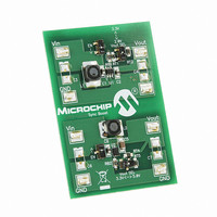
FIGURE 1-1:
The MCP1640 Synchronous Boost Converter Evaluation Board is used to evaluate and
demonstrate Microchip Technology’s MCP1640 products. This board demonstrates the
MCP1640 in two boost-converter applications with multiple output voltages. It can be
used to evaluate both package options (SOT-23-6 and 2x3-8 DFN). The MCP1640
Synchronous Boost Converter Evaluation Board was developed to help engineers
reduce the product design cycle time.
Three common output voltages can be selected: 2.0V, 3.3V and 5.0V. The output
voltage can be changed with a mini-dip switch that changes the external resistor
divider.
Chapter 1. Product Overview
0.9V To 1.7V
+
V
-
IN
CONVERTER EVALUATION BOARD
MCP1640 SYNCHRONOUS BOOST
4.7
Typical MCP1640 Boost Converter Single Cell Battery Input.
C
IN
µF
4.7
L
1
µH
V
EN
IN
SW
GND
V
OUT
V
FB
USER’S GUIDE
309 k
536 k
3.3V @ 100 mA
V
OUT
C
10
OUT
DS51880A-page 9
µF
Related parts for MCP1640EV-SBC
Image
Part Number
Description
Manufacturer
Datasheet
Request
R

Part Number:
Description:
0.65V Start-up Synchronous Boost Regulator with True Output Disconnect or Input/Output Bypass Option
Manufacturer:
MICROCHIP [Microchip Technology]
Datasheet:

Part Number:
Description:
IC CONV DC-DC STEPUP SYNC 8DFN
Manufacturer:
Microchip Technology
Datasheet:

Part Number:
Description:
0.65v Start-up Synchronous Boost Regulator With True Output Disconnect Or Input/output Bypass Option
Manufacturer:
Microchip Technology Inc.
Datasheet:
Part Number:
Description:
Manufacturer:
Microchip Technology Inc.
Datasheet:
Part Number:
Description:
Manufacturer:
Microchip Technology Inc.
Datasheet:
Part Number:
Description:
Manufacturer:
Microchip Technology Inc.
Datasheet:
Part Number:
Description:
Manufacturer:
Microchip Technology Inc.
Datasheet:
Part Number:
Description:
Manufacturer:
Microchip Technology Inc.
Datasheet:
Part Number:
Description:
Manufacturer:
Microchip Technology Inc.
Datasheet:
Part Number:
Description:
Manufacturer:
Microchip Technology Inc.
Datasheet: