RDK-115 Power Integrations, RDK-115 Datasheet - Page 3
RDK-115
Manufacturer Part Number
RDK-115
Description
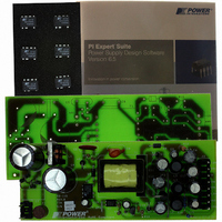
KIT REFERENCE DESIGN W/TN376PN
Manufacturer
Power Integrations
Series
TinySwitch®-PKr
Specifications of RDK-115
Main Purpose
AC/DC, Primary Side
Outputs And Type
4, Isolated
Power - Output
7.5W
Voltage - Output
3.3V, 5V, 12V, -12V
Current - Output
500mA, 500mA, 250mA, 30mA
Voltage - Input
85 ~ 265VAC
Regulator Topology
Flyback
Frequency - Switching
132kHz
Board Type
Fully Populated
Utilized Ic / Part
TNY376
Product
Accessories & Kits
Lead Free Status / RoHS Status
Not applicable / Not applicable
Other names
596-1145


Table of Contents
1
2
3
4
5
6
7
8
9
10
11
12
13
14
Page 3 of 36
4.1
4.2
4.3
4.4
7.1
7.2
7.3
7.4
7.5
7.6
9.1
9.2
9.3
9.4
11.1
11.2
11.3
11.4
11.5
11.6
13.1
Introduction .................................................................................................................5
Power Supply Specification ........................................................................................6
Schematic ...................................................................................................................7
Circuit Description.......................................................................................................8
PCB Layout...............................................................................................................10
Bill of Materials .........................................................................................................11
Transformer Specification .........................................................................................13
Design Spreadsheet .................................................................................................16
Performance Data.....................................................................................................18
9.1.1
9.4.1
9.4.2
11.5.1
11.5.2
Thermal Performance............................................................................................24
Waveforms ............................................................................................................25
Conducted EMI .....................................................................................................32
Appendix A............................................................................................................33
Revision History ....................................................................................................34
Input EMI Filtering................................................................................................8
TinySwitch-PK Primary ........................................................................................8
Output Feedback .................................................................................................9
Bypass/Multifunction Pin......................................................................................9
Electrical Diagram..............................................................................................13
Electrical Specifications .....................................................................................13
Materials ............................................................................................................13
Transformer Build Diagram................................................................................14
Copper Foil Preparation.....................................................................................14
Transformer Construction ..................................................................................15
Efficiency ...........................................................................................................18
No-load Input Power ..........................................................................................19
Available Standby Output Power .......................................................................20
Regulation .........................................................................................................21
Drain Voltage and Current, Normal Operation...................................................25
Output Voltage Start-up Profile ..........................................................................25
Drain Voltage and Current Start-up Profile ........................................................26
Load Transient Response..................................................................................26
Output Ripple Measurements ............................................................................29
Line Surge .........................................................................................................31
Output Power Delivery Using a TNY375P .........................................................33
Active Mode CEC Measurement Data........................................................18
Load Regulation, Room Temperature, 115 VAC input. ..............................21
Line.............................................................................................................23
Ripple Measurement Technique.................................................................29
Measurement Results.................................................................................30
Tel: +1 408 414 9200 Fax: +1 408 414 9201
Power Integrations
www.powerint.com
Related parts for RDK-115
Image
Part Number
Description
Manufacturer
Datasheet
Request
R

Part Number:
Description:
KIT REF DESIGN FOR LNK457D
Manufacturer:
Power Integrations
Datasheet:

Part Number:
Description:
REFERENCE DESIGN LINKSWITCH-PH
Manufacturer:
Power Integrations
Datasheet:

Part Number:
Description:
KIT REF DESIGN FOR LNK403EG
Manufacturer:
Power Integrations
Datasheet:

Part Number:
Description:
KIT REF DESIGN FOR LNK406EG
Manufacturer:
Power Integrations
Datasheet:

Part Number:
Description:
KIT REF DESIGN LINKSWITCH-CV
Manufacturer:
Power Integrations
Datasheet:

Part Number:
Description:
KIT REF DESIGN LINKSWITCH 2
Manufacturer:
Power Integrations
Datasheet:

Part Number:
Description:
Specifications: Family: Eval Boards - DC/DC & AC/DC (Off-Line) SMPS ; Series: HiperLCS™ ; Main Purpose: DC/DC, Step Down ; Outputs and Type: 1, Isolated ; Power - Output: 150W ; Voltage - Output: 24V ; Current - Output: 6.25A ; Voltage - Input:
Manufacturer:
Power Integrations, Inc.
Datasheet:

Part Number:
Description:
KIT DESIGN REF TINYSWITCH-III
Manufacturer:
Power Integrations
Datasheet:

Part Number:
Description:
KIT DESIGN REF LINKSWITCH LP
Manufacturer:
Power Integrations
Datasheet:

Part Number:
Description:
KIT REF DESIGN LED LINKSWITCH TN
Manufacturer:
Power Integrations
Datasheet:
Part Number:
Description:
KIT REF DESIGN PG LINKSWITCH-II
Manufacturer:
Power Integrations
Datasheet:
Part Number:
Description:
REFERENCE DESIGN LINKSWITCH-PL
Manufacturer:
Power Integrations
Datasheet:
Part Number:
Description:
REFERENCE DESIGN LINKSWITCH-PH
Manufacturer:
Power Integrations
Datasheet:

Part Number:
Description:
KIT REF DESIGN 36-72W MOTOR DRVR
Manufacturer:
Power Integrations
Datasheet:
Part Number:
Description:
Specifications: Manufacturer: Power Integrations ; Output Voltage: 380 VDC ; Input / Supply Voltage (Max): 264 VAC ; Input / Supply Voltage (Min): 90 VAC ; Mounting Style: Through Hole ; Output Current: 0.913 A ; Output Power: 347 W
Manufacturer:
Power Integrations, Inc.