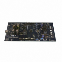
STEVAL-CBL006V1 STMicroelectronics, STEVAL-CBL006V1 Datasheet - Page 6

STEVAL-CBL006V1
Manufacturer Part Number
STEVAL-CBL006V1
Description
DEMO BOARD BASED ON LNBH24
Manufacturer
STMicroelectronics
Type
DC/DC Switching Converters, Regulators & Controllersr
Specifications of STEVAL-CBL006V1
Main Purpose
Special Purpose DC/DC, LNB
Outputs And Type
2, Non-Isolated
Voltage - Input
8 ~ 15V
Regulator Topology
Boost
Board Type
Fully Populated
Utilized Ic / Part
LNBH24
Input Voltage
12 V
Interface Type
I2C
Product
Power Management Modules
Supply Current
500 mA
Silicon Manufacturer
ST Micro
Silicon Core Number
LNBH24
Kit Application Type
Power Management
Application Sub Type
LNB Power Supply
Kit Contents
Board
Lead Free Status / RoHS Status
Lead free / RoHS Compliant
Current - Output
-
Voltage - Output
-
Power - Output
-
Frequency - Switching
-
Lead Free Status / Rohs Status
Lead free / RoHS Compliant
For Use With/related Products
LNBH24
Other names
497-8718
2.5
Figure 2.
2.6
2.7
6/30
be activated both with the DSQIN pin or the TEN I²C bit. The DSQIN internal circuit activates
the 22 kHz tone on the V
presence on the DSQIN pin, and it stops with 1 cycle ± 25 µs delay after the TTL signal is
expired.
Data encoding through external tone generator (EXTM)
In order to improve design flexibility an external tone input pin is available (EXTM). The
EXTM is a Logic input pin which activates the 22 kHz tone output, on the V
the LNBH24 integrated tone generator (similar to the DSQIN pin function). In fact, the output
tone waveform characteristics will always be internally controlled by the LNBH24 tone
generator and the EXTM signal will be used as a timing control for DiSEqC tone data
encoding on the V
control of the EXTM pin function. Before sending the TTL signal on the EXTM pin, the V
tone generator must be previously enabled through the TTX function (TTX pin or TTX bit set
HIGH). As soon as the EXTM internal circuit detects the 22 kHz TTL signal code, it activates
the 22 kHz tone on the V
presence on the EXTM pin, and it stops with 2 cycles ± 25 µs delay after the TTL signal is
expired (see
EXTM timings
I²C interface
The main functions of the IC are controlled via I²C BUS by writing 8 bits on the system
register (SR 8 bits in write mode). On the same register there are 8 bits that can be read
back (SR 8 bits in read mode) to provide 8 diagnostic functions: five bits will report the
diagnostic status of five internal monitoring functions (IMON, VMON, TMON, OTF, OLF),
while three will report the last output voltage register status (EN, VSEL, LLC) received by
the IC (see the diagnostic functions section). Each section (A/B) has two selectable I²C
addresses selectable, respectively, through the ADDR-A and ADDR-B pins (see address
pins characteristics
Output voltage selection
When the IC sections are in standby mode (EN bit LOW), the power blocks are disabled.
When the regulator blocks are active (EN bit HIGH), the output can be logic controlled to be
13 or 18 V by means of the VSEL bit (Voltage SELect) for remote controlling of non-DiSEqC
LNBs. Additionally, the LNBH24 is provided with the LLC I²C bit which increase the selected
voltage value by +1 V to compensate the excess of voltage drop along the coaxial cable.
Figure
oTX
Table
2).
output. A TTL-compatible 22 kHz signal is required for the proper
oTX
oTX
10).
output with 0.5 cycle ± 25 µs delay from the TTL signal
output with 1.5 cycles ± 25 µs delay from the TTL signal
oTX
pin, by using
oTX


