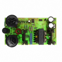
STEVAL-ISA019V2 STMicroelectronics, STEVAL-ISA019V2 Datasheet - Page 14

STEVAL-ISA019V2
Manufacturer Part Number
STEVAL-ISA019V2
Description
BOARD EVAL SMPS L6565 3PHASE APP
Manufacturer
STMicroelectronics
Type
Motor / Motion Controllers & Driversr
Specifications of STEVAL-ISA019V2
Mfg Application Notes
L6565/STC04IE170HV AppNote
Main Purpose
AC/DC, Primary Side
Outputs And Type
1, Isolated
Power - Output
80W
Voltage - Output
24V
Current - Output
3.33A
Voltage - Input
250 ~ 850V
Regulator Topology
Flyback
Board Type
Fully Populated
Utilized Ic / Part
L6565, STC04IE170HV
Input Voltage
250 V to 850 V
Output Voltage
24 V
Product
Power Management Modules
Lead Free Status / RoHS Status
Lead free / RoHS Compliant
Frequency - Switching
-
Lead Free Status / Rohs Status
Lead free / RoHS Compliant
For Use With/related Products
L6565, STC04IE170HV
Other names
497-6339
14/34
Base driving circuit design
I
and clamps the voltage across the small capacitor C
to the following empirical formulas and inside the range of V
Equation 27
The base peak current is higher with higher clamp voltage (D
which in turn will lead to shorter duration of the peak time.
The higher and longer the base peak current is, the lower the power dissipation during turn-
on. The designer must limit the I
Otherwise, at low load a very high saturation level may result. If the device is oversaturated,
the storage time is too long with higher power dissipation during turn-off. Moreover, a long
storage time can also lead to output oscillation, especially at high input voltage. To
overcome these problems, it is recommended to set the peak duration to 1/3 the minimum
duty cycle.
Following all the formulas mentioned in this section applied to the present work gives:
Equation 28
where A
saturation field B
From the first approximated assumption NS should be 10. From bench verification it is very
simple to verify that the turn ratio to get the best trade-off between conduction and turn-off
losses is 6.
Of course, this verification and final decision has been taken after setting all the other
components in the driving network and exactly:
Equation 29
Finally, the Zener has been set to 3 V.
peak
must be limited to avoid extra saturation of the device. The Zener diode D
e
t
peak
is the magnetic area, considering a ring core with 12.5 mm diameter, and the
=
3R
sat
b
is 400 mT.
C
c
V
Zmax
=
400ns
=
Doc ID 13127 Rev 4
2 I
(
=
b
peak
N
peak both in terms of amplitude and time duration.
C
TP
b
R
=
Figure 8
=
b
238nF
+
2
1
•
)
V
-------------------------------
1
A
•
e
=
shows the current transformer specifications:
T
•
onmax
C
B
sat
b
V
=
b
. The Zener must be chosen according
Zmin
220nF
≈
2
=
Zmin
2 I
(closet commercial value)
z
(
) or smaller capacitance (C
peak
and V
R
b
)
Zmax
:
z
controls this
AN2495
b
),


