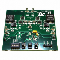
STEVAL-ISA053V1 STMicroelectronics, STEVAL-ISA053V1 Datasheet - Page 41

STEVAL-ISA053V1
Manufacturer Part Number
STEVAL-ISA053V1
Description
BOARD EVALUATION FOR PM6680
Manufacturer
STMicroelectronics
Type
DC/DC Switching Converters, Regulators & Controllersr
Specifications of STEVAL-ISA053V1
Design Resources
STEVAL-ISA053V1 Gerber Files PM6680 Eval Kit Schematic STEVAL-ISA053V1 Bill of Material
Main Purpose
DC/DC, Step Down with LDO
Outputs And Type
3, Non-Isolated
Voltage - Output
1.05V, 1.5V, 5V
Current - Output
5A, 5A, 100mA
Voltage - Input
6 ~ 28V
Regulator Topology
Buck
Frequency - Switching
200kHz, 300kHz
Board Type
Fully Populated
Utilized Ic / Part
PM6680
Input Voltage
6 V to 28 V
Output Voltage
5 V
Product
Power Management Modules
Silicon Manufacturer
ST Micro
Silicon Core Number
PM6680
Kit Application Type
Power Management - Voltage Regulator
Application Sub Type
Step Down DC/DC Controller
Kit Contents
Board
Lead Free Status / RoHS Status
Lead free / RoHS Compliant
Power - Output
-
Lead Free Status / Rohs Status
Lead free / RoHS Compliant
For Use With/related Products
PM6680
Other names
497-6378
Available stocks
Company
Part Number
Manufacturer
Quantity
Price
Company:
Part Number:
STEVAL-ISA053V1
Manufacturer:
STMicroelectronics
Quantity:
1
PM6680
Figure 39. Inductor current waveforms
Typical components values are: R=47 Ω and C = 1 uF.
●
●
●
Figure 40. Bootstrap circuit
The bootstrap circuit capacitor value C
side MOSFET during turn on phase. A typical value is 100nF.
The bootstrap diode D must charge the capacitor during the off time phases. The maximum
rated voltage must be higher than V
A resistor R
node rises up, working like a gate resistor for the turn on phase of the high side MOSFET.
VREF capacitor
A 10 nF to 100 nF ceramic capacitor on VREF pin must be added to ensure noise
rejection.
LDO5 output capacitors
Bypass the output of each linear regulator with 1 uF ceramic capacitor closer to the
LDO pin and a 4.7 uF tantalum capacitor (ESR = 2 Ω). In most applicative conditions a
4.7 uF ceramic output capacitor can be enough to ensure stability.
Bootstrap circuit
The external bootstrap circuit is represented in the next figure:
BOOT
on the BOOT pin could be added in order to reduce noise when the phase
L
L
INmax
BOOT
R
R
.
C
C
C
C
R
R
B
B
B
O
B
O
must provide the total gate charge to the high
O
O
O
O
O
O
T
T
D
D
T
T
B
P
B
P
H
O
H
O
L
A
L
A
O
O
L
L
V
V
D
D
S
S
D
D
T
C
C
T
O
O
E
E
O
O
C
C
5
5
5
5
Device description
41/49


