STEVAL-ISA051V2 STMicroelectronics, STEVAL-ISA051V2 Datasheet - Page 46
STEVAL-ISA051V2
Manufacturer Part Number
STEVAL-ISA051V2
Description
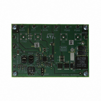
BOARD EVAL PM6670AS DDR2/3
Manufacturer
STMicroelectronics
Type
DC/DC Switching Converters, Regulators & Controllersr
Specifications of STEVAL-ISA051V2
Design Resources
STEVAL-ISA051V2 Gerber Files STEVAL-ISA051V2 Schematic STEVAL-ISA051V2 Bill of Material
Main Purpose
Special Purpose DC/DC, DDR Memory Supply
Outputs And Type
4, Non-Isolated
Voltage - Output
1.5V, 1.8V
Voltage - Input
4.5 ~ 36V
Regulator Topology
Buck
Board Type
Fully Populated
Utilized Ic / Part
PM6670A
Input Voltage
4.5 V to 36 V
Output Voltage
1.8 V, 1.5 V
Product
Power Management Modules
Silicon Manufacturer
ST Micro
Silicon Core Number
PM6670AS
Kit Application Type
Power Management
Application Sub Type
DDR2/3 Memory Power Supply Controller
Kit Contents
Board
Lead Free Status / RoHS Status
Lead free / RoHS Compliant
Current - Output
-
Power - Output
-
Frequency - Switching
-
Lead Free Status / Rohs Status
Lead free / RoHS Compliant
For Use With/related Products
PM6670AS
Other names
497-8412
Available stocks
Company
Part Number
Manufacturer
Quantity
Price
Company:

Part Number:
STEVAL-ISA051V2
Manufacturer:
STMicroelectronics
Quantity:
1


Application information
8.1.6
46/53
VDDQ current limit setting
The valley current limit is set by R
current. The valley of the inductor current I
Equation 45
The output current limit depends on the current ripple as shown I
Figure 39. Valley current limit waveforms
As the valley threshold is fixed, the greater the current ripple, the greater the DC output
current will be. If an output current limit greater than I
range is required, the minimum current ripple must be considered in the previous formula.
Then the resistor R
Equation 46
where R
temperature effect and the worst case value in R
The accuracy of the valley current also depends on the offset of the internal comparator
(±5 mV).
The negative valley-current limit (if the device works in forced-PWM mode) is given by:
Equation 47
DSon
is the drain-source on-resistance of the low-side switch. Consider the
MAX LOAD 1
Current
Valley current limit
CSNS
Inductor current
is:
Doc ID 14436 Rev 2
I
CSNS
Lvalley
R
CSNS
I
NEG
and must be chosen to support the maximum load
=
Inductor current
I
=
LOAD
Lvalley
MAX LOAD 2
=
R
DSon
120
R
(max)
100
DSon
DSon
is:
mV
⋅
uA
I
Lvalley
−
LOAD
calculation (typically +0.4%/°C).
Δ
2
I
L
(max) over all the input voltage
Figure 39
Time
:
PM6670AS
Related parts for STEVAL-ISA051V2
Image
Part Number
Description
Manufacturer
Datasheet
Request
R

Part Number:
Description:
BOARD RGB CTR ST7,STP08C596MTR
Manufacturer:
STMicroelectronics
Datasheet:

Part Number:
Description:
Power Management IC Development Tools Full Speed USB to RS232 Bridge Demo
Manufacturer:
STMicroelectronics
Datasheet:
Part Number:
Description:
Power Management IC Development Tools 2.5W solar eval BRD USB SPV1040 LD39050
Manufacturer:
STMicroelectronics
Datasheet:

Part Number:
Description:
BOARD EVAL FOR MEMS SENSORS
Manufacturer:
STMicroelectronics
Datasheet:

Part Number:
Description:
KIT DEV STARTER ST10F276Z5
Manufacturer:
STMicroelectronics
Datasheet:

Part Number:
Description:
BOARD EVAL HDMI $ VIDEO SWITCH
Manufacturer:
STMicroelectronics
Datasheet:

Part Number:
Description:
BOARD DEMO ACCELEROMETER DIL24
Manufacturer:
STMicroelectronics
Datasheet:

Part Number:
Description:
BOARD STLM75/STDS75/ST72F651
Manufacturer:
STMicroelectronics
Datasheet:

Part Number:
Description:
EVAL BOARD 3AXIS MEMS ACCELLRMTR
Manufacturer:
STMicroelectronics
Datasheet:

Part Number:
Description:
BOARD EVAL 8BIT MICRO + TDE1708
Manufacturer:
STMicroelectronics
Datasheet:
Part Number:
Description:
STMicroelectronics [RIPPLE-CARRY BINARY COUNTER/DIVIDERS]
Manufacturer:
STMicroelectronics
Datasheet:
Part Number:
Description:
STMicroelectronics [LIQUID-CRYSTAL DISPLAY DRIVERS]
Manufacturer:
STMicroelectronics
Datasheet:
Part Number:
Description:
BOARD EVAL FOR MEMS SENSORS
Manufacturer:
STMicroelectronics
Datasheet: