STEVAL-ISA041V1 STMicroelectronics, STEVAL-ISA041V1 Datasheet - Page 8
STEVAL-ISA041V1
Manufacturer Part Number
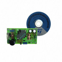
STEVAL-ISA041V1
Description
BOARD EVAL STP12IE95F4
Manufacturer
STMicroelectronics
Series
VIPER™r
Specifications of STEVAL-ISA041V1
Main Purpose
AC/DC, Primary Side
Outputs And Type
1, Isolated
Power - Output
125W
Voltage - Output
19V
Current - Output
6.6A
Voltage - Input
240 ~ 400VDC
Regulator Topology
Flyback
Frequency - Switching
55kHz
Board Type
Fully Populated
Utilized Ic / Part
L6565, STP12IE95F4
Product
Power Management Modules
Lead Free Status / RoHS Status
Lead free / RoHS Compliant
Other names
497-8410


L6565
Zero Current Detection and Triggering Block (see fig. 13):
The Zero Current Detection (ZCD) block switches on the external MOSFET if a negative-going edge falling be-
low 1.6 V is applied to the input (pin 5, ZCD). However, to ensure high noise immunity, the triggering block must
be armed first: prior to falling below 1.6V, the voltage on pin 5 must experience a positive-going edge exceeding
2.1 V.
This feature is typically used to detect transformer demagnetization for QR operation, where the signal for the
ZCD input is obtained from the transformer's auxiliary winding used also to supply the IC. Alternatively, this can
be used to synchronize MOSFET's turn-on to the negative-going edge of an external clock signal, in case the
device is not required to work in QR mode but as a standard PWM controller in a synchronized system (e.g.
monitor SMPS).
The triggering block is blanked for a certain time after the MOSFET has been turned off. This has two goals:
first, to prevent any negative-going edge that follows leakage inductance demagnetization from triggering the
ZCD circuit erroneously; second, to realize the Frequency Foldback function (see the relevant description).
Figure 13. Zero Current Detection and Triggering Block; Disable and Frequency Foldback Blocks
A circuit is needed that turns on the external MOSFET at start-up since no signal is coming from the ZCD pin.
This is realized with an internal starter, which forces the driver to deliver a pulse to the gate of the MOSFET.
To minimize the external interface with the synchronization source (either the auxiliary winding or an external
clock), the voltage at the pin is both top and bottom limited by a double clamp, as illustrated in the internal dia-
gram of the ZCD block of figure 13. The upper clamp is typically located at 5.2 V, while the lower clamp is at
one V
by and sunk from the pin within the rated capability of the internal clamps.
Disable Block (see fig. 13):
The ZCD pin is used also to activate the Disable Block. If the voltage on the pin is taken below 150 mV the de-
vice will be shut down. To do so, it is necessary to override the source capability (10 mA max.) of the internal
lower clamp. While in disable, the current consumption of the IC will be reduced. To re-enable device operation,
the pull-down on the pin must be released.
Frequency Foldback Block (see fig. 13):
To prevent the switching frequency from reaching too high values, which is a typical drawback of QR operation,
8/17
Q
BE
+Vin
above ground. The interface will then be made by just one resistor that has to limit the current sourced
R
ZCD
ZCD
5
L6565
0.2V
0.3V
1.6V
2.1V
+
+
-
-
5.2V
DISABLE
STABLE
MONO
BLANKING
TIME
COMP
STARTER
FFWD
to line
E/A
+
blanking
START
-
2.5V
starter STOP
INV
R
S
Q
PWM
DRIVER
7
GD
Related parts for STEVAL-ISA041V1
Image
Part Number
Description
Manufacturer
Datasheet
Request
R

Part Number:
Description:
BOARD RGB CTR ST7,STP08C596MTR
Manufacturer:
STMicroelectronics
Datasheet:

Part Number:
Description:
Power Management IC Development Tools Full Speed USB to RS232 Bridge Demo
Manufacturer:
STMicroelectronics
Datasheet:
Part Number:
Description:
Power Management IC Development Tools 2.5W solar eval BRD USB SPV1040 LD39050
Manufacturer:
STMicroelectronics
Datasheet:

Part Number:
Description:
BOARD EVAL FOR MEMS SENSORS
Manufacturer:
STMicroelectronics
Datasheet:

Part Number:
Description:
KIT DEV STARTER ST10F276Z5
Manufacturer:
STMicroelectronics
Datasheet:

Part Number:
Description:
BOARD EVAL HDMI $ VIDEO SWITCH
Manufacturer:
STMicroelectronics
Datasheet:

Part Number:
Description:
BOARD DEMO ACCELEROMETER DIL24
Manufacturer:
STMicroelectronics
Datasheet:

Part Number:
Description:
BOARD STLM75/STDS75/ST72F651
Manufacturer:
STMicroelectronics
Datasheet:

Part Number:
Description:
EVAL BOARD 3AXIS MEMS ACCELLRMTR
Manufacturer:
STMicroelectronics
Datasheet:

Part Number:
Description:
BOARD EVAL 8BIT MICRO + TDE1708
Manufacturer:
STMicroelectronics
Datasheet:
Part Number:
Description:
STMicroelectronics [RIPPLE-CARRY BINARY COUNTER/DIVIDERS]
Manufacturer:
STMicroelectronics
Datasheet:
Part Number:
Description:
STMicroelectronics [LIQUID-CRYSTAL DISPLAY DRIVERS]
Manufacturer:
STMicroelectronics
Datasheet:
Part Number:
Description:
BOARD EVAL FOR MEMS SENSORS
Manufacturer:
STMicroelectronics
Datasheet: