EVL6566B-65W-QR STMicroelectronics, EVL6566B-65W-QR Datasheet - Page 18
EVL6566B-65W-QR
Manufacturer Part Number
EVL6566B-65W-QR
Description
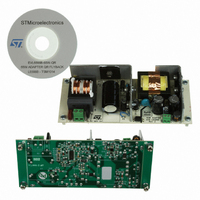
BOARD EVAL SMPS FOR L6566B
Manufacturer
STMicroelectronics
Type
Power Factor Correctionr
Specifications of EVL6566B-65W-QR
Main Purpose
AC/DC, Primary Side
Outputs And Type
1, Isolated
Power - Output
65W
Voltage - Output
700V
Voltage - Input
8 ~ 23 V
Regulator Topology
Flyback
Frequency - Switching
100kHz
Board Type
Fully Populated
Utilized Ic / Part
L6566B
Input Voltage
90 V to 265 V
Output Voltage
1.8 V to 12 V
Board Size
150 mm x 75 mm
Product
Power Management Modules
Dimensions
150 mm x 75 mm
Lead Free Status / RoHS Status
Lead free by exemption / RoHS compliant by exemption
Current - Output
-
Lead Free Status / Rohs Status
Lead free / RoHS Compliant
For Use With/related Products
L6566B
Other names
497-10165


Application information
5.1
18/51
If FF operation is selected:
1.
Equation 1
2.
The L6566B is specifically designed for applications with no PFC front-end; pin 6 (FMOD)
features an auxiliary oscillator that can modulate the switching frequency (when FF
operation is selected) in order to mitigate EMI emissions by a spread-spectrum action.
High-voltage start-up generator
Figure 5
It is made up of a high-voltage N-channel FET, whose gate is biased by a 15 MΩ resistor,
with a temperature-compensated current generator connected to its source.
Figure 5.
FF mode from heavy to light load. The system operates exactly like a standard current
mode control, at a frequency f
both DCM and CCM transformer operation are possible, depending on whether the
power that it processes is greater or less than:
where Vin is the input voltage to the converter, V
regulated output voltage times the primary-to-secondary turn ratio) and Lp the
inductance of the primary winding. Pin
continuous to discontinuous operation mode of the transformer.
Burst-mode with no or very light load. This kind of operation is activated in the same
way and results in the same behavior as previously described for QR operation.
shows the internal schematic of the high-voltage start-up generator (HV generator).
High-voltage start-up generator: internal schematic
L6566B
Vcc_OK
sw
determined by the externally programmable oscillator:
Pin
15 M
T
T
CONTROL
=
is the power level that marks the transition from
HV_EN
⎛
⎜ ⎜
⎝
Vin
GND
3
Vin
f 2
sw
+
V
V
1
R
Lp
HV
R
R
I
charge
I
HV
the reflected voltage (i.e. the
⎞
⎟ ⎟
⎠
2
5
Vcc
L6566B
Related parts for EVL6566B-65W-QR
Image
Part Number
Description
Manufacturer
Datasheet
Request
R

Part Number:
Description:
BOARD EVAL FOR L6566B
Manufacturer:
STMicroelectronics
Datasheet:

Part Number:
Description:
BOARD EVAL FOR L6566B
Manufacturer:
STMicroelectronics
Datasheet:

Part Number:
Description:
BOARD EVAL FOR L6566B
Manufacturer:
STMicroelectronics
Datasheet:

Part Number:
Description:
Power Management Modules & Development Tools L6566B-60WQR Eval Board
Manufacturer:
STMicroelectronics
Part Number:
Description:
STMicroelectronics [RIPPLE-CARRY BINARY COUNTER/DIVIDERS]
Manufacturer:
STMicroelectronics
Datasheet:
Part Number:
Description:
STMicroelectronics [LIQUID-CRYSTAL DISPLAY DRIVERS]
Manufacturer:
STMicroelectronics
Datasheet:

Part Number:
Description:
BOARD EVAL FOR MEMS SENSORS
Manufacturer:
STMicroelectronics
Datasheet:
Part Number:
Description:
NPN TRANSISTOR POWER MODULE
Manufacturer:
STMicroelectronics
Datasheet:
Part Number:
Description:
TURBOSWITCH ULTRA-FAST HIGH VOLTAGE DIODE
Manufacturer:
STMicroelectronics
Datasheet:
Part Number:
Description:
Manufacturer:
STMicroelectronics
Datasheet:
Part Number:
Description:
DIODE / SCR MODULE
Manufacturer:
STMicroelectronics
Datasheet:
Part Number:
Description:
DIODE / SCR MODULE
Manufacturer:
STMicroelectronics
Datasheet: