STEVAL-ISA029V1 STMicroelectronics, STEVAL-ISA029V1 Datasheet - Page 22
STEVAL-ISA029V1
Manufacturer Part Number
STEVAL-ISA029V1
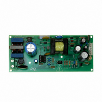
Description
BOARD EVAL BASED ON VIPER53-E
Manufacturer
STMicroelectronics
Series
VIPER™r
Type
MOSFET & Power Driverr
Specifications of STEVAL-ISA029V1
Design Resources
STEVAL-ISA029V1 Gerber Files STEVAL-ISA029V1 Schematic STEVAL-ISA029V1 Bill of Material
Main Purpose
AC/DC, Primary Side
Outputs And Type
3, Isolated
Power - Output
13W
Voltage - Output
12V, 3.3V, -24V
Current - Output
1A, 100mA, 40mA
Voltage - Input
85 ~ 300VAC
Regulator Topology
Flyback
Frequency - Switching
60kHz
Board Type
Fully Populated
Utilized Ic / Part
VIPer53
Input Voltage
85 V to 300 V
Output Voltage
12 V
Product
Power Management Modules
Silicon Manufacturer
ST Micro
Silicon Core Number
VIPer53-E
Kit Application Type
Power Management
Application Sub Type
Power Supply
Kit Contents
Board
Rohs Compliant
No
Lead Free Status / RoHS Status
Lead free / RoHS Compliant
For Use With/related Products
VIPer53-E
Other names
497-6458
STEVAL-ISA029V1
STEVAL-ISA029V1


High voltage Start-up current source
9
22/36
High voltage Start-up current source
An integrated high voltage current source provides a bias current from the DRAIN pin during
the start-up phase. This current is partially absorbed by internal control circuits in standby
mode with reduced consumption, and also supplies the external capacitor connected to the
V
UVLO logic, the device turns into active mode and starts switching. The start-up current
generator is switched off, and the converter should normally provide the needed current on
the V
page
The external capacitor C
the converter to start-up, when the device starts switching. This time tss depends on many
parameters, including transformer design, output capacitors, soft start feature, and
compensation network implemented on the COMP pin and possible secondary feedback
circuit.
The following formula can be used for defining the minimum capacitor needed:
Equation 5
Figure 21 on page 23
current I
down to I
rise. Device starts switching for V
energy to V
The charging current change at V
maintains a low restart duty cycle. This is especially useful for short circuits and overloads
conditions, as described in the following section.
DD
pin. As soon as the voltage on this pin reaches the high voltage threshold V
DD
17.
DDch1
pin through the auxiliary winding of the transformer, as shown on
DDch2
DD
at about 9 mA. When about V
capacitor after the start-up time tss.
which is about 0.6mA. This lower current leads to a slope change on the V
shows a typical start-up event. V
VDD
on the V
DD
DDoff
equal to V
DD
C
allows a fast complete start-up time t
VDD
pin must be sized according to the time needed by
DDoff
I
-------------------------- -
DD1
V
DDon
DDhyst
is reached, the charging current is reduced
, and the auxiliary winding delivers some
tss
DD
starts from 0V with a charging
Figure 19 on
SDU
, and
VIPer53 - E
DDon
of the
DD
Related parts for STEVAL-ISA029V1
Image
Part Number
Description
Manufacturer
Datasheet
Request
R

Part Number:
Description:
BOARD RGB CTR ST7,STP08C596MTR
Manufacturer:
STMicroelectronics
Datasheet:

Part Number:
Description:
Power Management IC Development Tools Full Speed USB to RS232 Bridge Demo
Manufacturer:
STMicroelectronics
Datasheet:
Part Number:
Description:
Power Management IC Development Tools 2.5W solar eval BRD USB SPV1040 LD39050
Manufacturer:
STMicroelectronics
Datasheet:

Part Number:
Description:
BOARD EVAL FOR MEMS SENSORS
Manufacturer:
STMicroelectronics
Datasheet:

Part Number:
Description:
KIT DEV STARTER ST10F276Z5
Manufacturer:
STMicroelectronics
Datasheet:

Part Number:
Description:
BOARD EVAL HDMI $ VIDEO SWITCH
Manufacturer:
STMicroelectronics
Datasheet:

Part Number:
Description:
BOARD DEMO ACCELEROMETER DIL24
Manufacturer:
STMicroelectronics
Datasheet:

Part Number:
Description:
BOARD STLM75/STDS75/ST72F651
Manufacturer:
STMicroelectronics
Datasheet:

Part Number:
Description:
EVAL BOARD 3AXIS MEMS ACCELLRMTR
Manufacturer:
STMicroelectronics
Datasheet:

Part Number:
Description:
BOARD EVAL 8BIT MICRO + TDE1708
Manufacturer:
STMicroelectronics
Datasheet:
Part Number:
Description:
STMicroelectronics [RIPPLE-CARRY BINARY COUNTER/DIVIDERS]
Manufacturer:
STMicroelectronics
Datasheet:
Part Number:
Description:
STMicroelectronics [LIQUID-CRYSTAL DISPLAY DRIVERS]
Manufacturer:
STMicroelectronics
Datasheet:
Part Number:
Description:
BOARD EVAL FOR MEMS SENSORS
Manufacturer:
STMicroelectronics
Datasheet: