EVL6566B-40WSTB STMicroelectronics, EVL6566B-40WSTB Datasheet - Page 34
EVL6566B-40WSTB
Manufacturer Part Number
EVL6566B-40WSTB
Description
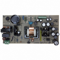
BOARD EVAL FOR L6566B
Manufacturer
STMicroelectronics
Datasheet
1.L6566BTR.pdf
(51 pages)
Specifications of EVL6566B-40WSTB
Main Purpose
AC/DC, Primary Side
Outputs And Type
4, Isolated
Power - Output
40W
Voltage - Output
5V, 12V, 1.8V, 3.3V
Current - Output
2.4A, 1.9A, 1.73A, 500mA
Voltage - Input
90 ~ 264VAC
Regulator Topology
Flyback
Frequency - Switching
62kHz
Board Type
Fully Populated
Utilized Ic / Part
L6566B
Product
Power Management Modules
Lead Free Status / RoHS Status
Lead free / RoHS Compliant
Other names
497-6450
Available stocks
Company
Part Number
Manufacturer
Quantity
Price


Application information
Note:
34/51
Figure 21. Soft-start pin operation under different operating conditions and settings
(pin 14)
(pin 5)
(pin 4)
COMP
(pin 9)
Vcc
GD
SS
2V
5V+2Vbe
START-UP
5V
The soft-start pin is also invoked whenever the control voltage (COMP) saturates high,
which reveals an open-loop condition for the feedback system. This condition very often
occurs at start-up, but may be also caused by either a control loop failure or a converter
overload/short circuit. A control loop failure results in an output overvoltage that is handled
by the OVP function of the L6566B (see next section). In case of QR operation, a short
circuit causes the converter to run at a very low frequency, then with very low power
capability. This makes the self-supply system that powers the device unable to keep it
operating, so that the converter will work intermittently, which is very safe. In case of
overload the system has a power capability lower than that at nominal load but the output
current may be quite high and overstress the output rectifier. In case of FF operation the
capability is almost unchanged and both short circuit and overload conditions are more
critical to handle.
The L6566B, regardless of the operating option selected, makes it easier to handle such
conditions: the 2 V clamp on the SS pin is removed and a second internal current generator
I
is allowed to reach 2 V
resulting behavior will be identical to that under short circuit illustrated in
page 20
Section 5.9: Latched disable function on page 32
A diode, with the anode to the SS pin and the cathode connected to the VREF pin (10) is the
simplest way to select either auto-restart mode or latch-mode behavior upon overcurrent. If
the overload disappears before the Css voltage reaches 5 V the I
turned off and the voltage gradually brought back down to 2 V. Refer to the “Application
examples and Ideas” section (
If latch-mode behavior is desired also for converter’s short circuit, make sure that the supply
voltage of the device does not fall below the UVLO threshold before activating the latch.
Figure 21
different settings (latch-mode or autorestart).
Unlike other PWM controllers provided with a soft-start pin, in the L6566B grounding the SS
pin does not guarantee that the gate driver is disabled.
SS2
= I
OPERATION
NORMAL
SS1
; in the latter case the result will be identical to that of
shows soft-start pin behavior under different operating conditions and with
/4 keeps on charging C
TEMPORARY
OVERLOAD
BE
over 5 V, the device will be latched off. In the former case the
Table 7 on page 45
OPERATION
NORMAL
SS
. As the voltage reaches 5 V the device is disabled, if it
OVERLOAD
Vcc falls below UVLO
before latching off
) for additional hints.
for additional details.
here the IC
shuts down
Figure 20 on page 33
SS2
SHUTDOWN
generator will be
AUTORESTART
here the IC
latches off
Figure 7 on
LATCHED
RESTART
L6566B
. See
UVLO
t
t
t
t
Related parts for EVL6566B-40WSTB
Image
Part Number
Description
Manufacturer
Datasheet
Request
R

Part Number:
Description:
BOARD EVAL SMPS FOR L6566B
Manufacturer:
STMicroelectronics
Datasheet:

Part Number:
Description:
BOARD EVAL FOR L6566B
Manufacturer:
STMicroelectronics
Datasheet:

Part Number:
Description:
BOARD EVAL FOR L6566B
Manufacturer:
STMicroelectronics
Datasheet:

Part Number:
Description:
Power Management Modules & Development Tools L6566B-60WQR Eval Board
Manufacturer:
STMicroelectronics
Part Number:
Description:
STMicroelectronics [RIPPLE-CARRY BINARY COUNTER/DIVIDERS]
Manufacturer:
STMicroelectronics
Datasheet:
Part Number:
Description:
STMicroelectronics [LIQUID-CRYSTAL DISPLAY DRIVERS]
Manufacturer:
STMicroelectronics
Datasheet:

Part Number:
Description:
BOARD EVAL FOR MEMS SENSORS
Manufacturer:
STMicroelectronics
Datasheet:
Part Number:
Description:
NPN TRANSISTOR POWER MODULE
Manufacturer:
STMicroelectronics
Datasheet:
Part Number:
Description:
TURBOSWITCH ULTRA-FAST HIGH VOLTAGE DIODE
Manufacturer:
STMicroelectronics
Datasheet:
Part Number:
Description:
Manufacturer:
STMicroelectronics
Datasheet:
Part Number:
Description:
DIODE / SCR MODULE
Manufacturer:
STMicroelectronics
Datasheet:
Part Number:
Description:
DIODE / SCR MODULE
Manufacturer:
STMicroelectronics
Datasheet: