STEVAL-ISA011V1 STMicroelectronics, STEVAL-ISA011V1 Datasheet - Page 10
STEVAL-ISA011V1
Manufacturer Part Number
STEVAL-ISA011V1
Description
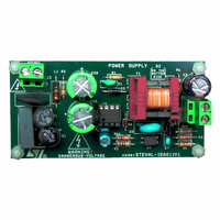
BOARD EVAL VIPER12A LP AC/DC
Manufacturer
STMicroelectronics
Series
VIPER™r
Type
AC/DC Switching Convertersr
Specifications of STEVAL-ISA011V1
Design Resources
STEVAL-ISA011V1 Gerber Files STEVAL-ISA011V1 Schematic STEVAL-ISA011V1 Bill of Materials
Main Purpose
AC/DC, Primary Side
Outputs And Type
1, Isolated
Power - Output
4.1W
Voltage - Output
4.5V
Current - Output
900mA
Voltage - Input
88 ~ 265VAC
Regulator Topology
Flyback
Frequency - Switching
60kHz
Board Type
Fully Populated
Utilized Ic / Part
VIPer12A
Input Voltage
88 V to 265 V
Output Voltage
4.5 V
Product
Power Management Modules
Silicon Manufacturer
ST Micro
Silicon Core Number
VIPER12ADIP-E
Kit Application Type
Power Management - Voltage Regulator
Application Sub Type
AC / DC Adapter
Kit Contents
Board
Rohs Compliant
No
Lead Free Status / RoHS Status
Lead free / RoHS Compliant
For Use With/related Products
VIPer12A
Other names
497-6413
STEVAL-ISA011V1
STEVAL-ISA011V1
Available stocks
Company
Part Number
Manufacturer
Quantity
Price


STEVAL-ISA011V1 Board Design
1.2.2
10/33
Transformer Turns Ratio and D
Equation 13
Equation 14
Equation 15
Equation 16
The turns ratio that is selected for the transformer depends on the output voltage, the
chosen reflected voltage, and the average voltage drop across the output diode.
Keeping in mind the voltage drop across its dynamic resistance, V
expressed as:
Where,
V
V
r
I
Using the calculated V
Where,
N
N
V
V
Using the calculated turns ratio, I
Where,
I
I
Note: The worst case (maximum power dissipation) will be in full load condition.
The D
Where,
D
L
f
O
PKS
PKP
SW
dD
P
O
DROP(avg)
dD
R
P
S
s_cond
= diode output current, and
= primary inductance, and
= reflected voltage, and
= Primary Turns,
= Secondary Turns,
= output voltage.
= dynamic resistance,
= switching frequency.
= drop voltage (when the diode is forward-biased),
= peak current at secondary winding, and
= peak power current
11
= Secondary Diode conduction duty cycle,
conduction duty cycle is expressed as:
= average voltage drop (across the output diode)
DROP(avg)
V
D
DROP avg
N
-------
N
s co nd
P
S
–
I
value, the turns ratio is expressed as:
Rev. 1
PKS
=
PKS
11
--------------------------------------------- -
V
O
is then expressed as:
=
Peak Current
=
+
I
-------------------------------------------- -
=
N
------ - I
N
PKP
V
V
P
S
DRO P avg
V
dD
R
V
L
PKP
+
R
P
r
dD
f
SW
I
O
AN2272 - Application Note
DROP(avg)
is
Related parts for STEVAL-ISA011V1
Image
Part Number
Description
Manufacturer
Datasheet
Request
R

Part Number:
Description:
BOARD RGB CTR ST7,STP08C596MTR
Manufacturer:
STMicroelectronics
Datasheet:

Part Number:
Description:
Power Management IC Development Tools Full Speed USB to RS232 Bridge Demo
Manufacturer:
STMicroelectronics
Datasheet:
Part Number:
Description:
Power Management IC Development Tools 2.5W solar eval BRD USB SPV1040 LD39050
Manufacturer:
STMicroelectronics
Datasheet:

Part Number:
Description:
BOARD EVAL FOR MEMS SENSORS
Manufacturer:
STMicroelectronics
Datasheet:

Part Number:
Description:
KIT DEV STARTER ST10F276Z5
Manufacturer:
STMicroelectronics
Datasheet:

Part Number:
Description:
BOARD EVAL HDMI $ VIDEO SWITCH
Manufacturer:
STMicroelectronics
Datasheet:

Part Number:
Description:
BOARD DEMO ACCELEROMETER DIL24
Manufacturer:
STMicroelectronics
Datasheet:

Part Number:
Description:
BOARD STLM75/STDS75/ST72F651
Manufacturer:
STMicroelectronics
Datasheet:

Part Number:
Description:
EVAL BOARD 3AXIS MEMS ACCELLRMTR
Manufacturer:
STMicroelectronics
Datasheet:

Part Number:
Description:
BOARD EVAL 8BIT MICRO + TDE1708
Manufacturer:
STMicroelectronics
Datasheet:
Part Number:
Description:
STMicroelectronics [RIPPLE-CARRY BINARY COUNTER/DIVIDERS]
Manufacturer:
STMicroelectronics
Datasheet:
Part Number:
Description:
STMicroelectronics [LIQUID-CRYSTAL DISPLAY DRIVERS]
Manufacturer:
STMicroelectronics
Datasheet:
Part Number:
Description:
BOARD EVAL FOR MEMS SENSORS
Manufacturer:
STMicroelectronics
Datasheet: