EVL6566B-65W STMicroelectronics, EVL6566B-65W Datasheet - Page 39
EVL6566B-65W
Manufacturer Part Number
EVL6566B-65W
Description
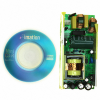
BOARD EVAL FOR L6566B
Manufacturer
STMicroelectronics
Specifications of EVL6566B-65W
Main Purpose
AC/DC, Primary Side
Outputs And Type
1, Isolated
Power - Output
65W
Voltage - Output
12V
Current - Output
5.4A
Voltage - Input
90 ~ 265VAC
Regulator Topology
Flyback
Frequency - Switching
80kHz
Board Type
Fully Populated
Utilized Ic / Part
L6566B
Product
Power Management Modules
Lead Free Status / RoHS Status
Lead free / RoHS Compliant
Other names
497-6452
Available stocks
Company
Part Number
Manufacturer
Quantity
Price


L6566B
Figure 26. Voltage sensing techniques to implement brownout protection with the
It is typically convenient to use a single divider to bias both the AC_OK and the VFF pins, as
shown in
is lower than that on the AC_OK pin. Once R
and k
Equation 18
Circuit a) senses the input voltage bus (across the bulk capacitor, downstream the bridge
rectifier); in this case, for a proper operation of the brownout function, Vsen
than the peak voltage at minimum mains and Vsen
the input bulk capacitor at minimum mains and maximum load considering, in case, holdup
requirements during mains missing cycles as well. Brownout level will be load-dependent. In
case of latched shutdown, when the input source is removed it is necessary to wait until the
bulk capacitor voltage falls below the start voltage of the HV generator V
the unit to restart, which may take even several seconds.
Circuit b) senses the mains voltage directly, upstream the bridge rectifier. It can be
configured either for half-wave sensing (only the line/neutral wire is sensed) or full-wave
sensing (both neutral and line are sensed); in the first case, assuming C
the sensed voltage will be equal to 1/
will be equal to 2/
to have small residual ripple superimposed on the dc level; as a rule-of-thumb, use a time
constant R
sensing, 2-3 times in case of full-wave sensing. Then fine tune if needed, considering also
transient conditions such as mains missing cycles. Brownout level will not depend on the
load. When the input source is removed C
circuit is suitable to have a quick restart after a latched shutdown.
The AC_OK pin is a high impedance input connected to high value resistors, thus it is prone
to pick up noise, which might alter the OFF threshold when the converter is running or give
origin to undesired switch-off of the device during ESD tests. It is possible to bypass the pin
to ground with a small film capacitor (e.g. 1-10 nF) to prevent any malfunctioning of this kind.
The voltage on the pin is clamped upwards at about 3.15 V; then, if the function is not used
the pin has to be connected to Vcc through a resistor (220 to 680 kΩ).
R
HV Input bus
L
opt
R
H
, either calculated from (6) or (8) or experimentally found, R
R
R
Figure 26
L1
L2
L
AC_OK
·C
L6566B
VFF
F
at least 4-5 times the maximum line cycle period in case of half-wave
π
16
15
a)
: this is possible because in all practical cases the voltage on the VFF pin
the peak mains voltage. C
OVPsettings
Optionalfor
L6566B
R
L
2
=
k
opt
(
R
π
L
the peak mains voltage, while in the second case it
+
AC mains (N/L)
R
F
H
will be discharged after some ten ms then this
H
)
F
and R
needs to be quite a big capacitor (in the uF)
;
OFF
R
R
L
H
L
have been found as suggested above,
1
AC mains (L/N)
R
lower than the minimum voltage on
=
L
R
R
H
L
−
R
R
L1
L2
R
b)
L
AC_OK
2
C
F
Application information
VFF
L
will be split as:
16
15
F
HVstart
is large enough,
ON
OVP settings
Optionalfor
L6566B
must be lower
in order for
39/51
Related parts for EVL6566B-65W
Image
Part Number
Description
Manufacturer
Datasheet
Request
R

Part Number:
Description:
BOARD EVAL SMPS FOR L6566B
Manufacturer:
STMicroelectronics
Datasheet:

Part Number:
Description:
BOARD EVAL FOR L6566B
Manufacturer:
STMicroelectronics
Datasheet:

Part Number:
Description:
BOARD EVAL FOR L6566B
Manufacturer:
STMicroelectronics
Datasheet:

Part Number:
Description:
Power Management Modules & Development Tools L6566B-60WQR Eval Board
Manufacturer:
STMicroelectronics
Part Number:
Description:
STMicroelectronics [RIPPLE-CARRY BINARY COUNTER/DIVIDERS]
Manufacturer:
STMicroelectronics
Datasheet:
Part Number:
Description:
STMicroelectronics [LIQUID-CRYSTAL DISPLAY DRIVERS]
Manufacturer:
STMicroelectronics
Datasheet:

Part Number:
Description:
BOARD EVAL FOR MEMS SENSORS
Manufacturer:
STMicroelectronics
Datasheet:
Part Number:
Description:
NPN TRANSISTOR POWER MODULE
Manufacturer:
STMicroelectronics
Datasheet:
Part Number:
Description:
TURBOSWITCH ULTRA-FAST HIGH VOLTAGE DIODE
Manufacturer:
STMicroelectronics
Datasheet:
Part Number:
Description:
Manufacturer:
STMicroelectronics
Datasheet:
Part Number:
Description:
DIODE / SCR MODULE
Manufacturer:
STMicroelectronics
Datasheet:
Part Number:
Description:
DIODE / SCR MODULE
Manufacturer:
STMicroelectronics
Datasheet: